The Crystal Structure Factor: Atomic Scattering, Diffraction Intensities, and Systematic Absences
1. Why do diffraction peaks have different intensities?
The positions of diffraction peaks are primarily determined by the unit-cell dimensions, crystal symmetry, and X-ray wavelength. Their intensities contain additional information: they depend on how the atoms are arranged inside the unit cell and how their scattered waves interfere.
The central quantity is the structure factor, (F_{hkl}). It is a complex amplitude obtained by adding the scattered-wave contributions from all atoms in the unit cell, including their phases.
For an ideal kinematic diffraction experiment, the intensity of a reflection is proportional to the squared magnitude of its structure factor:
\[ I_{hkl}\propto |F_{hkl}|^2. \]
This simple relationship is the foundation of crystallographic structure determination and the calculation of powder diffraction patterns.
2. From atomic scattering to the structure factor
Consider a unit cell containing (N) atoms. An atom at fractional coordinates ((x_j,y_j,z_j)) contributes to the scattering amplitude with a phase determined by its position relative to the reciprocal-lattice vector (_{hkl}).
Using the crystallographic convention for fractional coordinates, the phase factor is
\[ \exp\left[2\pi i(hx_j+ky_j+lz_j)\right]. \]
The structure factor is therefore
\[ \boxed{ F_{hkl}=\sum_{j=1}^{N} f_j \exp\left[2\pi i(hx_j+ky_j+lz_j)\right] } \]
where:
- (f_j) is the atomic scattering factor of atom (j);
- ((x_j,y_j,z_j)) are its fractional coordinates;
- (h,k,l) are the reflection indices;
- (i=).
The exponential contains the phase information. Two atoms with different coordinates can scatter with waves that reinforce or cancel one another for a particular reflection.
For a crystal with partial occupancies and isotropic atomic displacement parameters, a commonly used expression is
\[ F_{hkl}=\sum_j o_j f_j(s) \exp(-B_j s^2) \exp\left[2\pi i(hx_j+ky_j+lz_j)\right], \]
where (o_j) is the site occupancy, (B_j) is the isotropic displacement parameter, and (s=//(2d_{hkl})). Anisotropic displacement parameters require a direction-dependent Debye–Waller factor.
3. Understanding the phase factor
The phase angle contributed by atom (j) is
\[ \phi_j=2\pi(hx_j+ky_j+lz_j). \]
The corresponding complex contribution can be written as
\[ f_j e^{i\phi_j} =f_j(\cos\phi_j+i\sin\phi_j). \]
The real and imaginary components are summed separately:
\[ F_{hkl}=\operatorname{Re}(F_{hkl}) +i\operatorname{Im}(F_{hkl}). \]
The intensity contribution is
\[ |F_{hkl}|^2= [\operatorname{Re}(F_{hkl})]^2+ [\operatorname{Im}(F_{hkl})]^2. \]
A useful way to visualize this is as vector addition in the complex plane. Each atom contributes a vector whose length is related to its scattering factor and whose angle is its phase.
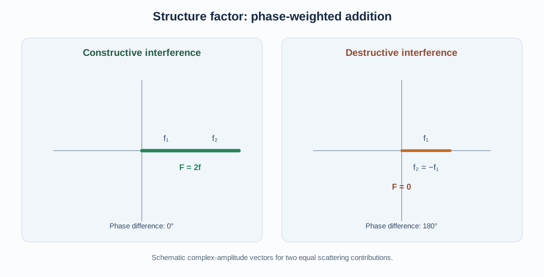
For two identical atoms with equal scattering factors:
- If their phase difference is zero, their amplitudes add.
- If their phase difference is (), their amplitudes cancel.
- At intermediate phase differences, partial constructive or destructive interference occurs.
This is why atomic coordinates determine reflection intensities and can also produce exact extinctions.
4. Atomic scattering factor
The atomic scattering factor (f) describes the X-ray scattering amplitude of an atom relative to that of a single electron, under the relevant scattering geometry. It depends on the element and on scattering angle (commonly represented through (/)).
Important practical points:
- At zero scattering angle, the normal atomic scattering factor is approximately related to the number of electrons in the atom.
- It generally decreases as scattering angle increases.
- Different elements have different scattering strengths, which provides chemical contrast in X-ray diffraction.
- Near an absorption edge, anomalous-dispersion corrections can be important.
The atomic scattering factor is not the same as the structure factor. The former describes an individual atom; the latter is the phase-weighted sum over the atoms in the unit cell.
For resonant or anomalous scattering, the atomic scattering factor is often written
\[ f=f_0+f'+if'', \]
where (f_0) is the normal scattering contribution and (f’), (f’’) are dispersion corrections.
5. Worked example: a two-atom basis
Consider two identical atoms with scattering factor (f), located at
\[ (0,0,0),\qquad \left(\frac{1}{2},\frac{1}{2},\frac{1}{2}\right). \]
Their structure factor is
\[ F_{hkl}=f\left[ 1+\exp\left(\pi i(h+k+l)\right) \right]. \]
Since ((im)=(-1)^m) for integer (m),
\[ F_{hkl}=f[1+(-1)^{h+k+l}]. \]
Therefore,
\[ F_{hkl}= \begin{cases} 2f,&h+k+l=2n,\\ 0,&h+k+l=2n+1. \end{cases} \]
Reflections with an even sum are allowed by this basis, while those with an odd sum are extinct. This is the familiar body-centering condition for a conventional I-centered lattice.
The result assumes identical atoms at the two positions. For a chemically different two-atom basis, the structure factor becomes
\[ F_{hkl}=f_A+f_B(-1)^{h+k+l}. \]
For odd sums this is (f_A-f_B), which is not generally zero. Thus, the extinction rule depends on the translational symmetry of the full crystal, not merely on a visual resemblance to a centered cell.
6. Structure factors of common cubic lattices
The centering translations contribute phase factors that produce characteristic reflection conditions.
Primitive cubic (P)
There is one lattice point at ((0,0,0)). For a monatomic primitive cubic lattice,
\[ F_{hkl}=f. \]
There is no additional centering extinction condition. This does not mean every measured peak must be present: the atomic basis, space-group symmetry, form factor, and experimental range still matter.
Body-centred cubic (I)
The conventional cell contains lattice points at
\[ (0,0,0),\qquad \left(\frac12,\frac12,\frac12\right). \]
For identical atoms,
\[ F_{hkl}=f[1+(-1)^{h+k+l}]. \]
The reflection condition is
\[ h+k+l=2n. \]
Examples: (110), (200), and (211) satisfy the condition; (100) and (111) do not.
Face-centred cubic (F)
The conventional cell has lattice points at
\[ (0,0,0),\quad \left(0,\frac12,\frac12\right),\quad \left(\frac12,0,\frac12\right),\quad \left(\frac12,\frac12,0\right). \]
For identical atoms,
\[ \begin{aligned} F_{hkl}=f[1 &+(-1)^{k+l} +(-1)^{h+l}\\ &+(-1)^{h+k}]. \end{aligned} \]
The result is non-zero when (h,k,l) are all even or all odd. Mixed parity gives systematic absence.
Examples: (111), (200), and (220) are allowed; (100), (110), and (210) are absent by F-centering.
These conditions are lattice-centering conditions. Additional basis atoms and space-group operations can introduce further intensity variations or absences.
7. Structure factor and measured intensity
The measured intensity is not simply (|F_{hkl}|^2) in every experimental context. For a powder diffraction pattern, the calculated integrated intensity of a reflection or reflection group is commonly represented schematically as
\[ I_{hkl}=S\,m_{hkl}\,L_{hkl}\,P_{hkl} \,A_{hkl}\,|F_{hkl}|^2, \]
where the exact factors and their definitions depend on the instrument geometry and refinement convention. Typical contributions include:
- (S): scale factor;
- (m_{hkl}): multiplicity;
- (L_{hkl}): Lorentz factor;
- (P_{hkl}): polarization factor;
- (A_{hkl}): absorption and related corrections, where applicable.
Preferred orientation, extinction, microabsorption in multiphase samples, peak overlap, and instrumental effects can also change observed intensities. The expression above is a conceptual decomposition, not a universal substitute for the instrument-specific intensity model.
For a powder pattern, symmetry-equivalent reflections can occur at the same d-spacing and contribute to the same peak. Their multiplicity must therefore be considered when comparing calculated and measured intensities.
8. Systematic absences: why can a reflection be exactly zero?
A systematic absence is a reflection forbidden by the translational component of a space-group symmetry operation. It is not simply a weak peak or a peak hidden by overlap.
The general structure-factor sum explains the origin. If symmetry-related atoms contribute phases that cancel exactly for a class of indices, then
\[ F_{hkl}=0 \]
for those reflections, independent of the values of the atomic scattering factors, provided the symmetry-related sites have the required equivalent scattering properties.
Common sources include:
- lattice centering (A, B, C, I, F, or R);
- screw axes, which combine rotation with fractional translation;
- glide planes, which combine reflection with fractional translation.
Screw-axis example: a 2₁ axis
For a 2₁ screw axis parallel to (b), the associated translation component is (b/2). For reflections along the reciprocal row (0k0), the screw-related phase contribution includes
\[ 1+\exp(2\pi i k/2)=1+(-1)^k. \]
Consequently, the condition is
\[ 0k0:\qquad k=2n. \]
Odd (k) reflections along this row are systematically absent due to the 2₁ screw axis.
Glide-plane example: a c-glide
A c-glide plane has a reflection component and a translation of (c/2). For the zone of reflections whose phase is unaffected by the reflection part, the translation gives a factor
\[ 1+\exp(2\pi i l/2)=1+(-1)^l. \]
For the corresponding glide-sensitive zone, odd (l) reflections are absent. The exact reflection condition must be read in the context of the glide-plane orientation, the chosen setting, and the space-group symbol; it should not be generalized to all ((hkl)) reflections.
9. Distinguishing systematic absences from weak reflections
A reflection can be weak without being forbidden. Several effects can produce low intensity:
- small atomic scattering contrast;
- destructive but incomplete interference;
- atoms located near positions that produce near-cancellation;
- high-angle reduction in atomic scattering factors;
- thermal motion and static disorder;
- occupancy or compositional effects.
A systematic absence is an exact symmetry-enforced zero in the ideal structure-factor model. In real data, background, multiple diffraction, defects, symmetry breaking, or experimental artifacts can produce weak intensity near a nominally forbidden position. Such intensity should be investigated rather than automatically interpreted as a violation of the space group.
10. How to use reflection conditions in space-group identification
Systematic absences provide constraints on possible space groups, but they rarely determine a unique space group by themselves.
A practical sequence is:
- Index the diffraction pattern and establish a plausible unit cell.
- Identify observed and unobserved reflections, accounting for the detection limit and peak overlap.
- Test lattice-centering conditions.
- Examine zone-specific conditions associated with screw axes and glide planes.
- Compare candidate space groups with intensity statistics, chemistry, and structural plausibility.
- Refine plausible models and inspect residuals, displacement parameters, occupancies, and difference maps.
Do not infer a space group from one missing peak. Confirm several independent reflection conditions and use the full diffraction dataset.
11. Practical workflow in GSAS-II
For a powder XRD refinement:
- Load the measured pattern and calibrate the wavelength and instrument parameters.
- Add a phase with the correct unit-cell setting and candidate space group.
- Confirm the atomic coordinates, element types, occupancies, and displacement parameters.
- Generate the calculated reflection list and compare allowed reflections with the measured pattern.
- Inspect whether missing peaks are predicted by the space group or merely too weak to detect.
- Refine the structural model only after checking phase identity, background, peak positions, and profile shape.
- Compare alternative space-group models when the data justify them; do not use a lower-symmetry model solely to fit noise.
GSAS-II calculates structure factors from the crystallographic model. VESTA is useful for checking the atomic arrangement and symmetry-generated positions, while a space-group reflection-condition reference can help interpret systematic absences.
12. Common mistakes
- Confusing the atomic scattering factor (f_j) with the unit-cell structure factor (F_{hkl}).
- Adding intensities directly instead of adding complex amplitudes and then taking the squared magnitude.
- Omitting fractional coordinates or using Cartesian coordinates in the phase expression.
- Forgetting occupancy and displacement-factor contributions.
- Applying BCC or FCC selection rules to a crystal whose full basis is not equivalent at every centering-related site.
- Treating a weak peak as a systematic absence.
- Assigning a space group from one missing reflection.
- Ignoring the crystallographic setting when applying glide- and screw-related conditions.
13. Key points
The structure factor is the phase-weighted sum of atomic scattering amplitudes within a unit cell. Its squared magnitude governs the intrinsic reflection intensity in the kinematic approximation. Atomic coordinates control phase interference; lattice centering, screw axes, and glide planes can impose systematic absences. Correct interpretation of an XRD pattern therefore requires both reciprocal-lattice geometry, which predicts reflection positions, and the structure factor, which predicts reflection intensities and extinctions.
Further reading
- The Reciprocal Lattice: Reciprocal Vectors, Crystal Planes, and X-ray Diffraction
- Miller Indices (hkl): Understanding Crystal Planes and Directions
- Understanding Crystallographic Space Groups
- Inversion, Mirror, Glide, and Screw Symmetry
- Reading and Interpreting XRD Patterns
- Rietveld Refinement with GSAS-II
References
- B. D. Cullity and S. R. Stock, Elements of X-Ray Diffraction, 3rd ed., Prentice Hall, 2001.
- International Union of Crystallography, International Tables for Crystallography, Volume A: Space-Group Symmetry.
- H. P. Klug and L. E. Alexander, X-ray Diffraction Procedures, 2nd ed., Wiley, 1974.
- B. E. Warren, X-ray Diffraction, Dover Publications, 1990.