Inversion, Mirror, Glide, and Screw Symmetry: A Comparative Crystallographic Guide
Inversion, Mirror, Glide, and Screw Symmetry: A Comparative Crystallographic Guide
In crystallography, inversion centres, mirror planes, glide planes and screw axes are distinct symmetry elements. They can all generate symmetry-related atomic positions, but they do so through different geometrical transformations. The distinction matters when interpreting a space-group symbol, expanding a CIF, assigning Wyckoff positions, and understanding systematic absences in diffraction.
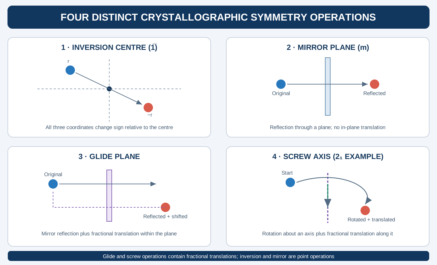
The most important conceptual separation is this:
- Inversion is a point operation through a centre.
- Mirror reflection is a reflection through a plane.
- Glide reflection is a mirror reflection combined with a translation parallel to the plane.
- Screw rotation is a rotation combined with a translation parallel to its axis.
This article develops each operation in fractional coordinates, compares their mathematical forms, and shows how to recognize them in crystallographic data.
1. General mathematical representation
A crystallographic symmetry operation can be written in fractional coordinates as
\[ \boxed{\mathbf{x}'=R\mathbf{x}+\mathbf{t}} \]
where
\[ \mathbf{x}=\begin{pmatrix}x\\y\\z\end{pmatrix}, \qquad \mathbf{x}'=\begin{pmatrix}x'\\y'\\z'\end{pmatrix} \]
and (R) is the rotational part while (t) is the translational part.
Two coordinate triplets that differ by integer lattice translations represent equivalent periodic positions. Thus, after applying an operation, coordinates can be reduced modulo one:
\[ (x',y',z')\equiv(x'+n_1,y'+n_2,z'+n_3) \]
where (n_1,n_2,n_3) are integers.
This convention is particularly useful when checking symmetry-generated positions from CIF files. It does not mean that arbitrary fractional translations are always valid: the operation must belong to the space group and preserve the periodic crystal structure.
2. Inversion symmetry
An inversion operation maps a point through an inversion centre. If the centre is at the origin, the transformation is
\[ \boxed{(x,y,z)\rightarrow(-x,-y,-z)} \]
and the matrix is
\[ R_{\mathrm{inv}}= \begin{pmatrix} -1&0&0\\ 0&-1&0\\ 0&0&-1 \end{pmatrix}, \qquad \mathbf t=\begin{pmatrix}0\\0\\0\end{pmatrix}. \]
The original point and its inversion mate are located on opposite sides of the centre, at equal distances. Applying inversion twice returns the original point:
\[ \mathbf{x}''=-(-\mathbf{x})=\mathbf{x}. \]
Inversion centre not at the origin
If the inversion centre is at (c=(c_x,c_y,c_z)), then
\[ \boxed{\mathbf{x}'=2\mathbf c-\mathbf{x}} \]
or, equivalently,
\[ \mathbf{x}'=-\mathbf{x}+2\mathbf c. \]
For example, an inversion centre at ((,0,0)) gives
\[ (x,y,z)\rightarrow(1-x,-y,-z). \]
Because fractional coordinates are periodic, the first coordinate can also be represented modulo an integer. This is why the origin choice must be considered before comparing coordinate expressions from different CIF files.
Worked example
Take an atom at
\[ A=(0.12,\;0.23,\;0.34). \]
Inversion through the origin gives
\[ A'=(-0.12,-0.23,-0.34). \]
Reducing each coordinate to the interval from 0 to 1 gives
\[ \boxed{A'=(0.88,\;0.77,\;0.66)}. \]
The structure has an inversion centre at the origin only if an equivalent atom (same species and compatible occupancy) is present at this generated position for every relevant site in the complete structure.
3. Mirror reflection
A mirror operation reflects a point through a plane. For a mirror plane perpendicular to the crystallographic (a)-axis and passing through the origin, the transformation is
\[ \boxed{(x,y,z)\rightarrow(-x,y,z)}. \]
Its matrix is
\[ R_m= \begin{pmatrix} -1&0&0\\ 0&1&0\\ 0&0&1 \end{pmatrix}. \]
The coordinate normal to the plane changes sign, while the two coordinates parallel to the plane remain unchanged.
Other examples include:
| Mirror plane | Coordinate transformation |
|---|---|
| Perpendicular to a | ((-x,y,z)) |
| Perpendicular to b | ((x,-y,z)) |
| Perpendicular to c | ((x,y,-z)) |
These expressions assume that the mirror plane passes through the origin and is aligned with the stated crystallographic axis. A plane displaced from the origin introduces a translation term. For example, a mirror plane at (x=) gives
\[ (x,y,z)\rightarrow(\tfrac12-x,y,z). \]
What is fixed by a mirror operation?
Every point lying exactly on the mirror plane remains unchanged. Points away from the plane are mapped to corresponding points on the opposite side.
A mirror operation is not the same as inversion. Inversion changes the signs of all three coordinates (for an origin-centred inversion), whereas a mirror perpendicular to (a) changes only the sign of (x).
4. Glide-plane symmetry
A glide plane combines a mirror reflection with a fractional translation parallel to the mirror plane. Its general form is
\[ \boxed{\mathbf{x}'=R_m\mathbf{x}+\mathbf{t}_{\parallel}} \]
where the translation vector lies in the mirror plane.
For a glide plane perpendicular to (a), a possible glide translation parallel to (b) is
\[ (x,y,z)\rightarrow(-x,y+\tfrac12,z). \]
This is a b-glide plane in this orientation. The reflection changes the coordinate normal to the plane, while the half-cell translation shifts the position along the plane.
Common glide symbols
| Glide symbol | Fractional translation component |
|---|---|
| a | (a) |
| b | (b) |
| c | (c) |
| n | Half translation along a suitable face diagonal |
| d | Diamond glide, involving characteristic quarter translations |
| e | Double glide, with two glide translations in the plane |
The exact allowed glide operation depends on the plane orientation, lattice type and space-group setting. In particular, the n-, d- and e-glide descriptions should be interpreted using the conventional crystallographic setting rather than by assuming one universal coordinate expression.
Why glide planes matter in XRD
The fractional translation can cause cancellation between scattering contributions from symmetry-related atoms. Consequently, glide planes impose systematic reflection conditions for certain zones or classes of reflections.
The reflection condition depends on the glide-plane orientation and the direction of its translation. One should consult the reflection conditions for the actual space group and setting rather than infer a universal condition from the letter alone.
5. Screw-axis symmetry
A screw operation combines a rotation about an axis with a fractional translation parallel to that axis.
A screw axis is denoted by (n_m), where:
- (n) is the order of the rotation;
- the rotation angle is (360^/n);
- (m/n) is the fractional translation along the axis per operation, in the conventional description.
For example, a (2_1) screw axis parallel to (c) can be represented by
\[ (x,y,z)\rightarrow(-x,-y,z+\tfrac12). \]
The operation rotates the point by 180° about the axis and translates it by half a unit-cell repeat along (c).
Common screw axes
| Screw axis | Rotation per operation | Translation along axis |
|---|---|---|
| (2_1) | 180° | () |
| (3_1) | 120° | () |
| (3_2) | 120° | () |
| (4_1) | 90° | () |
| (4_2) | 90° | () |
| (4_3) | 90° | () |
| (6_1) | 60° | () |
| (6_2) | 60° | () |
| (6_3) | 60° | () |
| (6_4) | 60° | () |
| (6_5) | 60° | () |
The translation is understood modulo a full lattice repeat. For example, a (4_3) operation translates by three quarters of the repeat, equivalent to a negative quarter translation under a different choice of direction.
Repeated application of a screw operation
After (n) applications of an (n_m) screw operation, the rotational part returns to the original orientation, while the accumulated translation is (m) full lattice repeats:
\[ n\left(\frac{m}{n}\right)=m. \]
Since (m) is an integer, the resulting displacement is a lattice translation. This is consistent with the periodicity of the crystal.
6. Direct comparison of the four operations
| Feature | Inversion | Mirror | Glide | Screw |
|---|---|---|---|---|
| Geometrical element | Centre | Plane | Plane | Axis |
| Point operation | Inversion | Reflection | Reflection | Rotation |
| Fractional translation | Not required | Not required | Parallel to plane | Parallel to axis |
| Changes coordinates | All components relative to centre | Component normal to plane | Normal component plus in-plane shift | Rotated components plus axial shift |
| Typical notation | (1) | m | a, b, c, n, d, e | (n_m) |
| Can generate systematic absences? | Not as a general centering-type condition by itself | Not by itself in the same way as glide/screw translations | Yes | Yes |
A key point in the final row is that systematic absences are associated with translational components of symmetry and lattice centering. Inversion and pure mirror operations can affect intensity symmetry relations, but they do not impose the same characteristic translational extinction conditions as glide planes and screw axes.
7. How to distinguish these operations in a CIF file
A CIF may provide symmetry operations as coordinate strings, for example:
x,y,z
-x,-y,-z
-x,y,z
-x,y+1/2,z
-x,-y,z+1/2
These expressions illustrate, respectively:
- Identity.
- Inversion through the origin.
- Mirror perpendicular to (a), through the origin.
- A b-glide perpendicular to (a), with half translation along (b).
- A (2_1) screw operation parallel to (c).
This is a teaching example, not a complete list for one space group. A real space group contains a complete set of operations consistent with closure and the lattice translations.
When interpreting an operation string:
- Identify the signs and permutations of (x,y,z). These indicate the point-operation part.
- Identify fractional constants such as (), (), or (). These may indicate glide or screw translations.
- Determine whether the translation is parallel to a mirror plane or rotation axis.
- Check the space-group setting and origin.
- Apply the operation to a test coordinate and reduce the result modulo integer translations.
- Verify that the generated positions are consistent with the reported atomic sites and occupancies.
Do not classify an operation from a single plus or minus sign alone. The complete coordinate transformation and its geometrical orientation are required.
8. Symmetry operations and reflection conditions
The structure factor for a reflection ((hkl)) is
\[ F(hkl)=\sum_j f_j\exp\left[2\pi i(hx_j+ky_j+lz_j)\right]. \]
When symmetry-related atoms are present, their scattering contributions can add constructively or cancel. A fractional translation can produce a phase factor. For a translation (t=(t_x,t_y,t_z)), the phase contribution associated with reflection ((hkl)) is
\[ \exp\left[2\pi i(ht_x+kt_y+lt_z)\right]. \]
For selected reflection classes, symmetry-related contributions may sum to zero. This is the origin of systematic absences associated with centering translations, screw axes and glide planes.
A missing or weak experimental peak is not automatically a systematic absence. Peak overlap, preferred orientation, low intensity, absorption, detector limits and sample quality can all affect observed intensities. Reflection conditions should be assessed using the full diffraction dataset and the candidate space-group setting.
9. Common conceptual errors
- Calling every reflection a mirror operation: an XRD reflection is a diffracted beam indexed by ((hkl)), not a mirror plane.
- Treating inversion as a mirror: inversion changes all three coordinates relative to a centre; a mirror changes the coordinate normal to a plane.
- Calling a glide plane a simple mirror: a glide includes a fractional translation within the plane.
- Calling a screw axis a pure rotation: a screw operation includes translation along the axis.
- Ignoring the origin: the same physical symmetry can have different coordinate expressions in different origin choices.
- Assuming every absent peak is symmetry-forbidden: experimental limitations can suppress intensity without a true systematic absence.
- Inferring a unique space group from one operation: the complete set of operations and the lattice must be mutually consistent.
10. Practical checklist
When analysing a structure:
- Record the space-group symbol, number and setting.
- Read the symmetry-operation list from the CIF.
- Separate each operation into its matrix part (R) and translation part (t).
- Identify whether the point operation is inversion, reflection or rotation.
- Check whether a fractional translation is present.
- Determine the orientation of the plane or axis.
- Generate symmetry-equivalent atomic coordinates and compare them with the structural model.
- Compare the expected reflection conditions with the measured diffraction pattern.
Key takeaways
- Inversion maps a point through a centre; mirror symmetry reflects it through a plane.
- A glide plane is a reflection plus an in-plane fractional translation.
- A screw axis is a rotation plus a translation parallel to the rotation axis.
- Fractional translations associated with glide and screw operations are important sources of systematic absences in diffraction.
- Coordinate expressions depend on the space-group setting and origin choice.
- CIF symmetry-operation strings should be interpreted as complete transformations, not classified from isolated symbols.
Further reading
- International Union of Crystallography, International Tables for Crystallography, Volume A: Space-Group Symmetry. https://it.iucr.org/A/.
- International Union of Crystallography, Online Dictionary of Crystallography. https://dictionary.iucr.org/.
- Bilbao Crystallographic Server. https://www.cryst.ehu.es/.
- C. Giacovazzo et al., Fundamentals of Crystallography, 3rd edition, Oxford University Press.