Miller Indices (hkl): Understanding Crystal Planes and Directions
1. What are Miller indices?
Miller indices are integer labels used to describe the orientation of lattice planes and crystallographic directions. They are central to crystallography because they connect the geometry of a unit cell to diffraction, crystal morphology, anisotropic properties, and materials processing.
The notation must be distinguished carefully:
- ((hkl)): one lattice-plane orientation (a plane or a member of that orientation set);
- ({hkl}): a family of symmetry-equivalent planes;
- ([uvw]): one crystallographic direction;
- (uvw): a family of symmetry-equivalent directions.
For example, in a cubic crystal, (100), (010), and (001) are symmetry-equivalent members of the {100} family. They are not the same physical plane, but they have equivalent orientations under cubic symmetry.
2. How to calculate Miller indices from plane intercepts
The conventional procedure uses the intercepts made by a plane with the crystallographic axes, expressed in units of the corresponding lattice parameters.
- Determine the intercepts along (a), (b), and (c).
- Express each intercept as a multiple of its lattice parameter.
- Take the reciprocals of those three values.
- Clear fractions to obtain the smallest set of integers.
- Write the result as ((hkl)).
If a plane is parallel to an axis, its intercept is at infinity and the reciprocal is zero. If a plane passes through the origin, choose a parallel plane in the same family that does not pass through the origin before determining the intercepts.
Worked example. Suppose a plane intercepts the axes at (2a), (3b), and (c). The intercepts in lattice units are ((2,3,1)). Their reciprocals are ((1/2,1/3,1)). Multiplying by 6 gives
\[ (hkl)=(3\ 2\ 6). \]
The integers are conventionally written without commas: (326).
Examples of common intercepts
| Intercepts in lattice units | Reciprocals | Miller indices |
|---|---|---|
| ((1,,)) | ((1,0,0)) | (100) |
| ((,1,)) | ((0,1,0)) | (010) |
| ((,,1)) | ((0,0,1)) | (001) |
| ((1,1,1)) | ((1,1,1)) | (111) |
| ((2,3,1)) | ((1/2,1/3,1)) | (326) |
A negative intercept produces a negative Miller index, represented by a bar over the corresponding integer, for example (({1}10)).
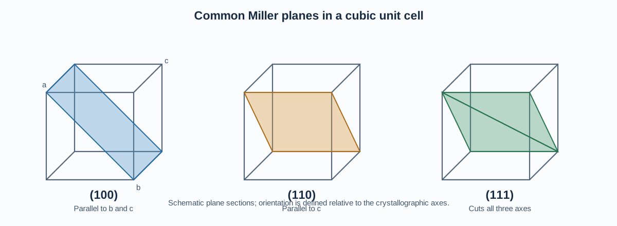
3. Visual interpretation of common planes
In a cubic cell:
- is parallel to the (b) and (c) axes and cuts the (a) axis at one lattice parameter.
- cuts the (a) and (b) axes at one lattice parameter and is parallel to (c).
- cuts all three axes at one lattice parameter.
The indices describe orientation, not a unique position. Translating a plane parallel to itself does not change its Miller indices.
4. Negative indices and the overbar notation
A negative intercept means that the plane meets the negative side of an axis. Its Miller index is written with an overbar:
\[ (\bar{1}01),\qquad (1\bar{1}0),\qquad (\bar{1}\bar{1}1). \]
The overbar applies only to the integer immediately below it. In plain-text CIF or software fields, negative integers may appear with a minus sign rather than a typographic overbar.
5. Miller indices of directions: [uvw]
Directions are not calculated by taking reciprocals of plane intercepts. A direction is represented by a vector parallel to the crystallographic direction.
To determine [uvw]:
- Choose two points on the direction.
- Subtract the fractional coordinates of the starting point from those of the ending point.
- Express the resulting vector in the crystallographic basis.
- Clear fractions and reduce to the smallest integer ratio.
- Write the result in square brackets.
For example, a direction with fractional displacement ((1/2,1,0)) is reduced by multiplying by 2:
\[ [uvw]=[1\ 2\ 0]. \]
The direction [120] is a vector direction in the lattice basis; it is not a plane index.
For non-cubic systems, be careful when interpreting directions geometrically. The integer triplet gives components along the direct-lattice basis vectors, which need not be perpendicular or equal in length.
6. The zone law: checking whether a direction lies in a plane
For a direction [uvw] to lie in a plane (hkl) in the conventional three-index notation, it must satisfy the zone law:
\[ hu+kv+lw=0. \]
For example, [1{1}0] lies in (110), because
\[ 1(1)+1(-1)+0(0)=0. \]
This is a useful algebraic check when indexing directions in a crystal plane. The reciprocal-lattice normal and direct-lattice direction are distinct concepts; the zone law expresses their orthogonality through the index components.
7. Interplanar spacing, d(hkl)
The interplanar spacing (d_{hkl}) is the perpendicular distance between adjacent parallel planes belonging to the same family. It depends on the lattice parameters and the Miller indices.
Cubic crystals
For a cubic unit cell with lattice parameter (a),
\[ d_{hkl}=\frac{a}{\sqrt{h^2+k^2+l^2}}. \]
Example: for a cubic material with (a=4.00) Å, the spacing of the (110) planes is
\[ d_{110}=\frac{4.00}{\sqrt{1^2+1^2+0^2}} =2.828\ \text{Å}. \]
Tetragonal crystals
For (a=bc) and all angles equal to 90°,
\[ \frac{1}{d_{hkl}^{2}} =\frac{h^2+k^2}{a^2}+\frac{l^2}{c^2}. \]
Orthorhombic crystals
For mutually perpendicular axes with unequal lengths,
\[ \frac{1}{d_{hkl}^{2}} =\frac{h^2}{a^2}+\frac{k^2}{b^2}+\frac{l^2}{c^2}. \]
General crystal systems
For a general unit cell, the spacing is most safely calculated using the reciprocal-lattice metric. If the reciprocal basis vectors are defined without the factor (2), then
\[ \frac{1}{d_{hkl}^{2}} = h^2a^{*2}+k^2b^{*2}+l^2c^{*2} +2klb^*c^*\cos\alpha^* +2hl a^*c^*\cos\beta^* +2hk a^*b^*\cos\gamma^*. \]
Here (a*,b,c^) and (*,,^) are the reciprocal-cell parameters. This form avoids applying cubic or orthogonal-cell formulae to lower-symmetry lattices.
8. Connection between Miller indices and X-ray diffraction
In powder X-ray diffraction, a reflection is associated with a set of lattice planes satisfying the diffraction condition. For first-order Bragg diffraction,
\[ n\lambda=2d_{hkl}\sin\theta, \]
where () is the X-ray wavelength, (d_{hkl}) is the interplanar spacing, and () is the Bragg angle.
Combining Bragg’s law with the cubic spacing equation gives
\[ \sin^2\theta =\frac{\lambda^2}{4a^2} (h^2+k^2+l^2) \]
for first-order diffraction.
This relationship is useful for indexing cubic powder patterns: the ratios of (^2) values are related to the allowed values of (h2+k2+l^2). However, not every geometrically possible (hkl) reflection is necessarily observed. Systematic absences caused by lattice centering, glide planes, and screw axes must also be considered, and reflection intensities depend on the structure factor.
A powder peak is therefore not assigned from its position alone without considering the unit cell, symmetry, and reflection conditions.
9. Important distinction: plane indices and diffraction indices
The notation (hkl) is used both for a family of lattice planes and for the reciprocal-lattice vector associated with a diffraction reflection. These concepts are closely connected but should not be conflated.
The reciprocal-lattice vector is
\[ \mathbf{G}_{hkl}=h\mathbf{a}^{*} +k\mathbf{b}^{*}+l\mathbf{c}^{*}, \]
when the reciprocal basis is defined without (2). It is normal to the corresponding (hkl) planes, and
\[ |\mathbf{G}_{hkl}|=\frac{1}{d_{hkl}}. \]
Thus, in a cubic crystal, the [hkl] direction is perpendicular to the (hkl) plane. This simple parallelism does not generally hold in non-cubic crystals because the direct and reciprocal bases are not identical.
10. Families of planes and directions
Curly braces and angle brackets denote symmetry-related families:
- ({100}): all planes equivalent to (100) under the crystal’s symmetry;
- ({110}): all symmetry-equivalent planes of the (110) type;
- (): all symmetry-equivalent directions of the [100] type.
The actual members of a family depend on the crystal symmetry. A cubic crystal has more equivalent orientations in {100} than a tetragonal crystal, for example. Do not assume that sign changes and permutations are all symmetry-equivalent in every crystal system.
11. Practical workflow in VESTA and XRD analysis
In VESTA
- Open the CIF and confirm the unit-cell parameters and space group.
- Display the unit-cell axes and choose the plane or direction tool.
- Enter the Miller indices in the appropriate plane or direction field.
- Check whether the displayed plane has the expected intercepts and orientation.
- Confirm the view against the lattice axes; do not infer indices from screen orientation alone.
In powder XRD and Rietveld analysis
- Determine or verify the unit-cell parameters and space group.
- Calculate candidate (d_{hkl}) values for the lattice system.
- Convert between (d) and (2) using Bragg’s law and the experimental wavelength.
- Apply the reflection conditions of the space group.
- Compare calculated peak positions with the measured pattern.
- Use the structural model and calculated intensities to validate the indexing.
For GSAS-II, the phase symmetry and lattice parameters define the allowed reflection list. A correct indexing model should explain the peak positions consistently, while the structural model determines the calculated intensities.
12. Common mistakes
- Taking reciprocals of direction components when calculating [uvw].
- Confusing (hkl), {hkl}, [uvw], and
. - Forgetting that an axis-parallel plane has a zero index for that axis.
- Failing to shift a plane that passes through the origin before using the intercept method.
- Applying the cubic d-spacing equation to tetragonal, orthorhombic, or lower-symmetry cells.
- Assuming [hkl] is perpendicular to (hkl) in every crystal system.
- Treating every possible geometric reflection as allowed, without checking systematic absences.
- Assuming the same permutations and sign changes form a family in every space group.
13. Key points
Miller indices provide a compact description of lattice-plane orientations and crystallographic directions. Plane indices are obtained from reciprocal intercepts, whereas direction indices come from vector components. Interplanar spacing is determined by the reciprocal lattice and the unit-cell metric. In XRD, each indexed reflection connects a plane spacing to a diffraction angle through Bragg’s law, but symmetry and structure-factor conditions determine which reflections can occur and how intense they are.
Further reading
- Crystal Structures and the Seven Crystal Systems
- Symmetry Elements and Symmetry Operations in Crystals
- Understanding Crystallographic Space Groups
- Understanding Wyckoff Positions in Crystallography
- Fractional Coordinates and Symmetry-Equivalent Atomic Positions
- Reading and Interpreting XRD Patterns
- Rietveld Refinement with GSAS-II
References
- B. D. Cullity and S. R. Stock, Elements of X-Ray Diffraction, 3rd ed., Prentice Hall, 2001.
- International Union of Crystallography, International Tables for Crystallography, Volume A: Space-Group Symmetry.
- M. F. C. Ladd and R. A. Palmer, Structure Determination by X-ray Crystallography, 4th ed., Springer, 2003.
- B. E. Warren, X-ray Diffraction, Dover Publications, 1990.