Crystal Structures and the Seven Crystal Systems: A Practical Guide
Crystal structure is the geometrical framework used to describe the periodic arrangement of atoms, ions or molecules in a crystalline material. It connects atomic-scale arrangement to measurable properties such as diffraction, anisotropic transport, mechanical response and phase stability. This guide introduces the crystallographic language needed to read structural models and interpret powder X-ray diffraction (XRD) results.
1. Lattice, basis and crystal structure
A lattice is an infinite periodic array of points. A basis is the atom or group of atoms associated with each lattice point. The crystal structure is obtained by placing the same basis at every lattice point.
A translation vector can be written as
[ =u+v+w ]
where (), () and () are the unit-cell basis vectors and (u,v,w) are integers. The unit cell is a repeating volume that generates the lattice by translation.
The conventional unit cell is selected to display the symmetry clearly. A primitive unit cell contains exactly one lattice point when boundary sharing is counted correctly. The conventional cell is often larger but easier to visualize and use.
2. The six lattice parameters
A unit cell is defined by three edge lengths and three interaxial angles:
- (a,b,c): lengths of the crystallographic axes.
- (): angle between (b) and (c).
- (): angle between (a) and (c).
- (): angle between (a) and (b).
The seven crystal systems are distinguished by constraints on these six parameters. The constraints describe metric symmetry; the full crystal symmetry also depends on the allowed symmetry operations and atomic arrangement.
3. The seven crystal systems
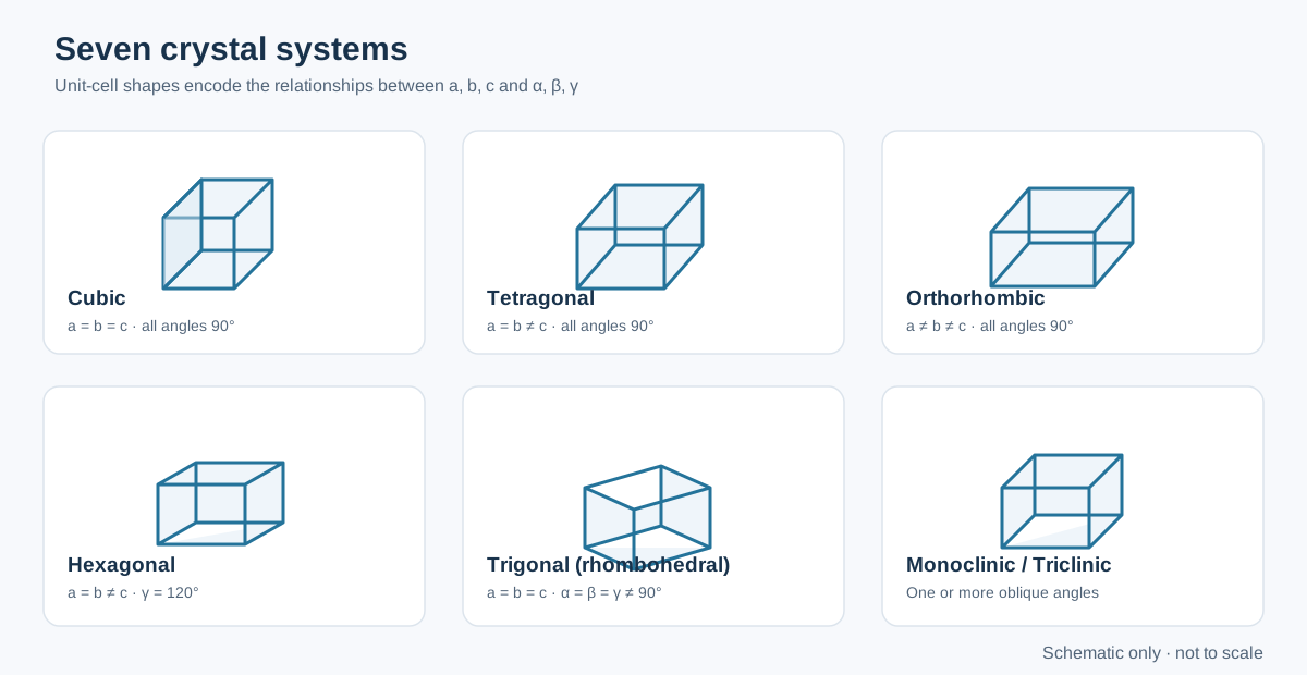
| Crystal system | Axial lengths | Interaxial angles | Example |
|---|---|---|---|
| Cubic | (a=b=c) | (==^) | NaCl, SrTiO₃ (cubic phase) |
| Tetragonal | (a=bc) | All 90° | TiO₂ (rutile) |
| Orthorhombic | (abc) | All 90° | BaSO₄ |
| Hexagonal | (a=bc) | (=,) | ZnO (wurtzite) |
| Trigonal (rhombohedral) | (a=b=c) | (==^) in rhombohedral axes | Calcite |
| Monoclinic | (abc) | Two angles 90°, one differs | Monoclinic ZrO₂ |
| Triclinic | (abc) | All angles unequal to 90° in the general case | CuSO₄·5H₂O |
Important distinction: trigonal is a crystal system, while rhombohedral describes a common lattice setting for it. Trigonal structures can also be described using hexagonal axes. The chosen setting must be stated when reporting lattice parameters.
What the systems mean physically
- Cubic: equivalent axes and right angles give high metric symmetry. Cubic materials are often isotropic in second-rank properties, although higher-rank properties and microstructure can still be direction-dependent.
- Tetragonal: one axis differs in length, producing a unique crystallographic direction.
- Orthorhombic: three unequal perpendicular axes.
- Hexagonal: a sixfold rotational symmetry is characteristic of the system; the conventional hexagonal cell uses (^).
- Trigonal: threefold symmetry is characteristic. Do not identify a structure as trigonal solely because a hexagonal-looking cell is used.
- Monoclinic: one non-right angle in the conventional unique-axis setting.
- Triclinic: the least constrained metric system; no cell angle is required to be 90°.
4. Bravais lattices: centering matters
A crystal system does not uniquely specify the lattice. Lattice centering describes where equivalent lattice points occur within the conventional cell:
- P (primitive): lattice points only at the corners.
- I (body-centred): corners plus one point at the cell centre.
- F (face-centred): corners plus one point at the centre of each face.
- C (base-centred): corners plus points at the centres of one pair of opposite faces.
- R (rhombohedral): rhombohedral lattice, commonly represented in a hexagonal setting.
There are 14 Bravais lattices in three dimensions. Not every centering type is compatible with every crystal system. For example, cubic has P, I and F lattices; tetragonal has P and I; orthorhombic has P, C, I and F. The hexagonal system has P, while the trigonal system has R. Monoclinic has P and C, and triclinic has P.
Counting lattice points in a conventional cell
A corner point is shared by eight cells, a face-centred point by two cells, and an edge-centred point by four cells. Therefore:
[ N=+++N_{inside} ]
For common cells: - Primitive: (8(1/8)=1) lattice point. - Body-centred: (8(1/8)+1=2). - Face-centred: (8(1/8)+6(1/2)=4).
These are lattice points, not necessarily atoms. The number of atoms per cell also depends on the basis attached to each lattice point.
5. Unit-cell volume
For a general triclinic unit cell, the volume is
[ V=abc ]
Use consistent angular units in the calculation. Special cases simplify:
- Cubic: (V=a^3)
- Tetragonal: (V=a^2c)
- Orthorhombic: (V=abc)
- Hexagonal: (V=a^2c)
For monoclinic cells in the common unique-(b) setting, (V=abc). Always confirm the axis convention used by the crystallographic file or refinement software.
6. Miller indices: describing planes and directions
Miller indices describe crystallographic planes. The procedure for a plane is:
- Determine its intercepts with the crystallographic axes in units of (a,b,c).
- Take the reciprocals of the intercepts.
- Clear fractions to obtain the smallest integer set ((hkl)).
- An intercept at infinity gives a reciprocal of zero.
For example, intercepts ((1,1,)) give reciprocals ((1,1,0)), so the plane is (110). A plane parallel to an axis has zero for the corresponding index.
A family of symmetry-equivalent planes is written ({hkl}), while a direction is written ([uvw]) and a family of directions (uvw). Parentheses, square brackets, braces and angle brackets are not interchangeable. Negative indices are written with an overbar, for example (({1}10)).
Interplanar spacing and diffraction
For a cubic crystal:
[ d_{hkl}= ]
For a hexagonal crystal in the conventional setting:
[ = + ]
These relations connect a structural model to peak positions through Bragg’s law:
[ n=2d_{hkl} ]
A peak assignment must be consistent with the lattice, systematic absences, plausible phases and the measurement wavelength. A list of calculated d-spacings alone does not establish phase identity.
7. Crystallographic density
The theoretical crystallographic density is calculated from the mass in the unit cell divided by its volume:
[ _{x-ray}= ]
where (Z) is the number of formula units per unit cell, (M) is the molar mass of the formula unit, (N_A) is Avogadro’s constant, and (V) is the unit-cell volume. Use compatible units; if (V) is in ų, convert it using (1,3=10{-24},^3).
For a compositionally substituted oxide, calculate (M) from the actual nominal or refined composition and state which was used. Vacancies, non-stoichiometry and mixed valence can change the formula mass and should not be ignored when they are significant.
The theoretical density is not the same as the bulk density of a sintered pellet. Open and closed pores lower the measured bulk density. Relative density is commonly expressed as
[ D_{relative}(%)= ]
The comparison is meaningful only when the theoretical density corresponds to the correct phase and composition and the bulk-density method is appropriate.
8. From a CIF file to an experimental interpretation
A Crystallographic Information File (CIF) commonly stores: - Unit-cell lengths and angles. - Space-group information and symmetry operations. - Atomic species, fractional coordinates and occupancies. - Displacement parameters and refinement metadata, when available.
Before using a CIF in GSAS-II or another refinement package, verify the chemical formula, space group, cell setting, occupancies and coordinate conventions. A CIF downloaded from a database is a structural starting model, not proof that your sample has that exact structure.
For an experimental powder pattern, a defensible workflow is:
- Identify plausible phases using composition and synthesis conditions.
- Compare peak positions and systematic absences with candidate structures.
- Check whether the proposed space group and cell setting are internally consistent.
- Refine a justified model and inspect the difference curve and parameter uncertainties.
- Compare refined composition and density with independent chemical or physical measurements where possible.
9. Common mistakes
- Confusing crystal system with space group. There are seven crystal systems but 230 space groups.
- Confusing a unit cell with a single molecule or formula unit. A cell may contain several formula units and a multi-atom basis.
- Assuming every cubic material is body-centred. Cubic P, I and F lattices are all possible.
- Treating Miller indices as Cartesian directions. In non-cubic systems, a plane normal and a direction with the same indices are not generally parallel.
- Using the wrong cell setting. Hexagonal and rhombohedral settings can describe trigonal structures; parameters cannot be mixed between settings.
- Inferring a complete structure from one diffraction peak. Peak overlap, preferred orientation and secondary phases must be considered.
10. Practical checklist for reporting a crystal structure
Report the phase name and chemical composition, crystal system, space group and setting, lattice parameters with uncertainties, unit-cell volume, radiation wavelength, refinement method and fit indicators. If density is reported, state the formula mass, (Z), cell volume and assumptions used. For substituted or defective oxides, clarify whether occupancies were fixed to nominal values or refined.
Further reading
- International Tables for Crystallography, Volume A: Space-Group Symmetry, IUCr.
- C. Giacovazzo et al., Fundamentals of Crystallography, 3rd ed., Oxford University Press (2011).
- B. D. Cullity and S. R. Stock, Elements of X-Ray Diffraction, 3rd ed., Prentice Hall (2001).
- R. A. Young (ed.), The Rietveld Method, Oxford University Press (1993).