High-Temperature Furnaces: Heating, Atmosphere and Temperature Control
High-Temperature Furnaces
PROCESSING & THERMAL EQUIPMENT · TOPIC 03.01 · CONTROLLED HEAT TREATMENT
A laboratory furnace establishes a controlled thermal environment for calcination, sintering, annealing, crystallization, reaction synthesis and other heat treatments. The programmed setpoint is not automatically the true specimen temperature: sensor location, thermal gradients, loading, atmosphere and controller dynamics all matter.
1. Main furnace architectures
Common laboratory systems include box/muffle furnaces, tube furnaces, vacuum or controlled-atmosphere furnaces, and specialized high-temperature systems. Their differences concern chamber geometry, gas handling, heating-element placement, usable temperature range, contamination control and temperature uniformity.
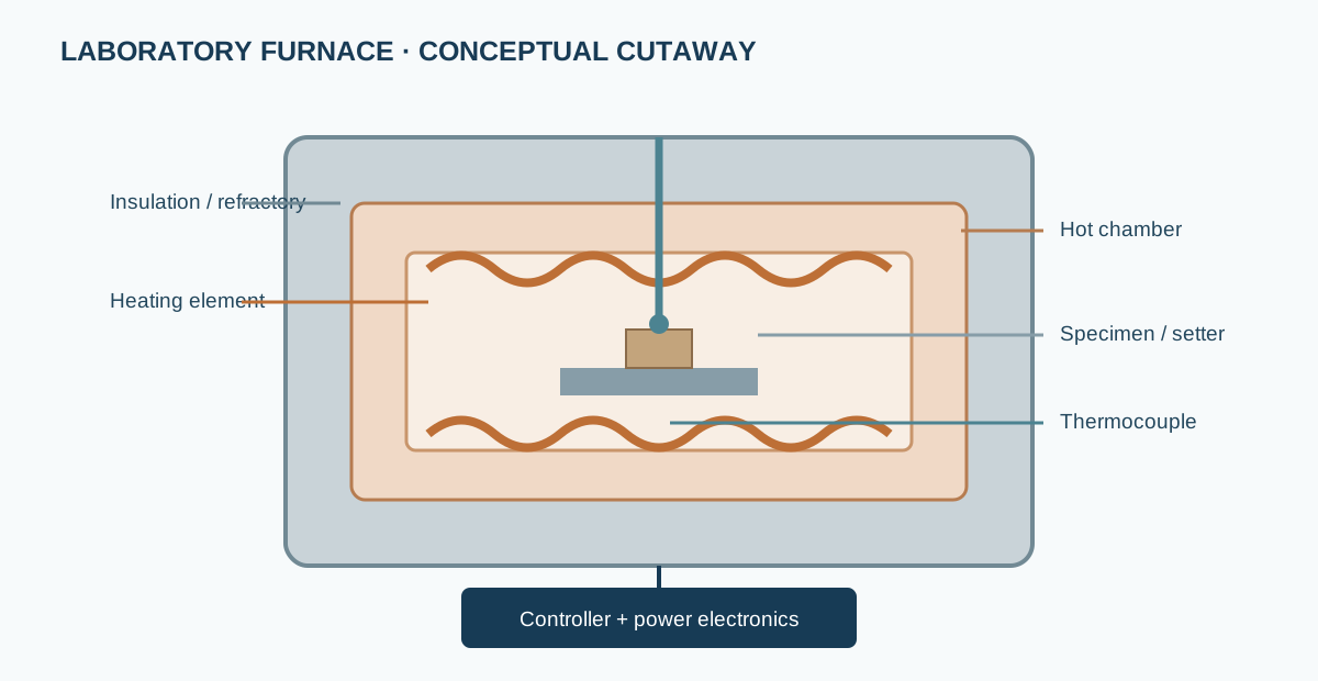
A typical resistive furnace contains: - heating elements that convert electrical power to heat; - refractory insulation and a hot-zone enclosure; - a chamber, tube or retort that contains the specimen; - a thermocouple or other temperature sensor; - a controller and power switching electronics; - optional gas inlet, outlet, flow control and pressure protection; - specimen supports, setters and crucibles.
The actual architecture is manufacturer- and model-specific. A muffle furnace, tube furnace and retort furnace should not be assumed to have interchangeable atmosphere or temperature capabilities.
2. Heating elements and insulation
Heating elements may use metallic alloys, silicon carbide, molybdenum disilicide or other materials selected for temperature, atmosphere and service life. Element oxidation, volatilization, contamination and resistance drift can limit use. Refractory insulation reduces heat loss and helps establish a stable hot zone, but insulation type and condition affect maximum temperature and thermal cycling.
Never infer atmosphere compatibility from the maximum temperature rating alone. Consult the furnace and element documentation for oxidizing, inert, reducing or vacuum conditions.
3. Temperature sensing and control
A thermocouple generates a temperature-dependent electromotive force. The controller converts this signal using the selected thermocouple type and reference-junction compensation. Incorrect sensor type, polarity, extension wire, compensation or calibration can cause substantial temperature error.
A PID controller compares measured temperature with the setpoint and adjusts heater power. In simplified form:
[ e(t)=T_{set}(t)-T_{meas}(t) ]
The proportional, integral and derivative terms influence response, offset and overshoot. The optimum tuning depends on furnace thermal mass, loading, sensor position and heating power.
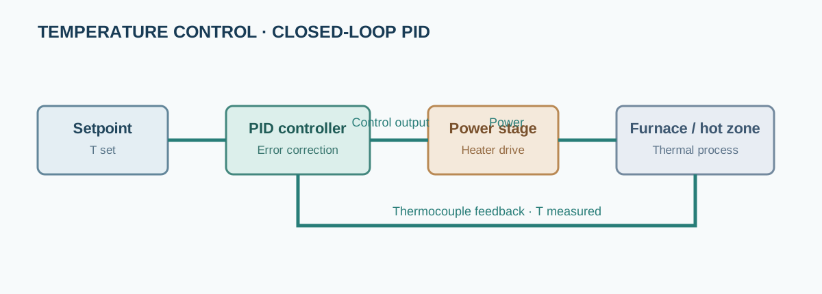
A controller display is a measurement at the sensor location, not a direct measurement of every point in the chamber or the specimen core.
4. Hot zone, working zone and uniformity
The rated maximum temperature is a limit, not a statement of uniformity. The usable working zone is the region where temperature remains within a specified tolerance under defined loading and operating conditions.
Uniformity can change with: - specimen mass, position and spacing; - crucible and setter materials; - door opening and chamber condition; - heating rate and dwell time; - gas flow and thermal conductivity of the atmosphere; - ageing of elements, insulation and sensors.
Use a calibrated reference sensor or a temperature-mapping study when the process requires a defined uniformity. Record sensor position and loading configuration.
5. Atmosphere and gas handling
Air, inert gas, oxidizing mixtures, reducing gas and vacuum impose different chemical and safety requirements. Gas purity, flow, leakage, pressure, dew point and chamber materials can affect phase stability and defect chemistry.
A nominal gas-cylinder label does not establish the oxygen partial pressure at the specimen. Consider leaks, residual chamber air, gas-line dead volume, reactions with setters and outgassing from insulation. Reducing and combustible gases require engineered ventilation, gas detection, purge sequences and approved interlocks.
6. Designing a reproducible firing schedule
A complete thermal profile specifies: - initial condition and any pre-drying step; - ramp rate for each segment; - target temperature and dwell time; - atmosphere, flow and pressure conditions; - specimen position, crucible, setter and loading; - cooling rate or controlled atmosphere changes; - sensor type, calibration status and location.
For ceramic synthesis, separate calcination, binder removal and sintering where the chemistry or gas evolution requires it. Avoid assuming that a longer dwell always improves phase purity or density: volatilization, grain growth, secondary phases and crucible reactions may worsen.
7. Practical operating workflow
- Confirm the furnace model, rated operating envelope and atmosphere compatibility.
- Inspect chamber, elements, insulation, thermocouple and door seals.
- Select compatible crucibles and setters; check for reactions or contamination.
- Place specimens within the validated working zone and avoid obstructing sensors.
- Verify thermocouple type, polarity, controller program and over-temperature protection.
- Establish gas purge and exhaust using the approved sequence, if applicable.
- Run the programmed ramp/dwell/cooling profile and log actual temperature.
- Allow safe cooling before opening; follow material- and atmosphere-specific restrictions.
- Inspect specimens and supports for reaction, contamination, cracking or volatilization.
- Record deviations and repeatability.
8. Common errors and troubleshooting
| Observation | Possible cause | Diagnostic check |
|---|---|---|
| Specimen under-reacted despite correct display | Sensor-to-specimen gradient, poor loading position | Map temperature and verify specimen location |
| Overshoot | PID tuning, sensor lag, excessive ramp rate | Compare setpoint and independent sensor trace |
| Different results between runs | Loading, crucible, gas flow or sensor drift | Standardize and document full configuration |
| Unexpected secondary phase | Atmosphere, contamination, volatilization or reaction with setter | Blank/setter tests and phase analysis |
| Element failure | Thermal cycling, contamination or atmosphere incompatibility | Inspect element and operating history |
| Temperature unstable | Sensor fault, loose connection, power control issue | Check sensor circuit and controller alarms |
9. Calibration, verification and reporting
Distinguish calibration of the temperature sensor from verification of the complete furnace working zone. A calibrated thermocouple does not prove chamber uniformity. Use traceable reference sensors and documented mapping procedures appropriate to the required temperature and uncertainty.
Report furnace manufacturer/model, heating-element type where known, sensor type and location, calibration status, working-zone position, sample loading, crucible/setter, atmosphere composition and flow, pressure, ramp/dwell/cooling profile and any deviations.
10. Manufacturers and technical documentation
- Nabertherm — laboratory and industrial furnaces.
- Carbolite Gero — laboratory and high-temperature furnaces.
- Yamato Scientific — laboratory heating equipment.
- Thermo Fisher Scientific — laboratory furnace and thermal equipment portfolio.
Use the exact model manual for rated temperature, atmosphere compatibility, sensor type, working-zone specification, maintenance and safety interlocks.
Interactive laboratory: furnace temperature control
Explore ramp response and PID tuning
Change target, ramp demand, controller gains and thermal load. Compare the idealized chamber response with the programmed profile.
Teaching model, not a furnace simulator or tuning prescription. It omits radiation nonlinearity, sensor placement, multi-zone coupling and real controller implementation. Use measured temperature data and the exact controller procedure for actual tuning.