Thermal Analysis: TGA, DSC and DTA
Thermal Analysis: TGA, DSC and DTA
MATERIALS CHARACTERIZATION · TOPIC 01.05 · THERMAL RESPONSE
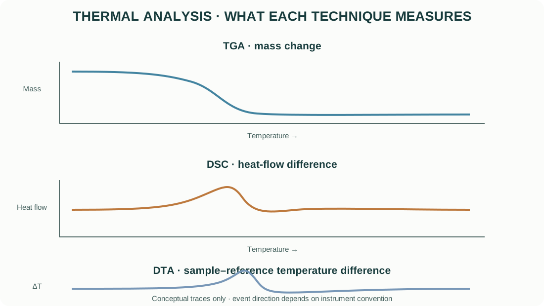
Thermal analysis measures how a material responds while its temperature is controlled or programmed. Thermogravimetric analysis (TGA), differential scanning calorimetry (DSC) and differential thermal analysis (DTA) are related techniques, but they measure different quantities.
- TGA: change in sample mass as a function of temperature or time.
- DSC: difference in heat flow between a sample and a reference, under a defined temperature program.
- DTA: temperature difference between a sample and a reference as both are subjected to a controlled thermal program.
These techniques are used to study dehydration, decomposition, oxidation, reduction, crystallization, phase transitions, melting, glass transitions, reaction kinetics and thermal stability. The atmosphere, heating rate, sample mass, crucible and gas flow can change the observed response.
1. What is measured?
Thermogravimetric analysis (TGA)
TGA measures sample mass while the specimen is heated, cooled or held isothermally. The output is commonly mass (or normalized mass percent) versus temperature or time.
A derivative thermogravimetric curve (DTG) plots the rate of mass change, often (dm/dT) or (dm/dt). DTG peaks help locate the temperature range where a mass-loss or mass-gain process is fastest.
TGA can detect processes involving mass change, such as: - removal of physically adsorbed water; - dehydration and dehydroxylation; - decomposition of carbonates, hydroxides or organic precursors; - oxidation or reduction when gas exchange changes specimen mass; - combustion or volatilization.
A process with no net mass change may not produce a TGA step. For example, a solid–solid phase transition can be visible in DSC or DTA without a measurable mass change.
Differential scanning calorimetry (DSC)
DSC measures the heat-flow difference between a sample and a reference under a controlled temperature program. The output is typically heat flow versus temperature or time.
Depending on the instrument design, DSC may use a heat-flux arrangement or a power-compensation arrangement. The sign convention for endothermic and exothermic events varies by instrument and software. Always inspect the instrument’s convention before assigning peak direction.
DSC can detect: - melting and crystallization; - glass transitions; - solid-state phase transitions; - curing and reaction enthalpies; - heat-capacity changes; - some oxidation and decomposition events.
Differential thermal analysis (DTA)
DTA measures the temperature difference between a sample and a reference as both experience the same programmed thermal environment. Endothermic and exothermic events cause a temperature difference because the sample and reference respond differently.
DTA peak area is not automatically an enthalpy. Quantitative enthalpy measurement requires calibration and an appropriate measurement model; DSC is commonly preferred for heat-flow and enthalpy measurements.
2. How a thermal analyser works
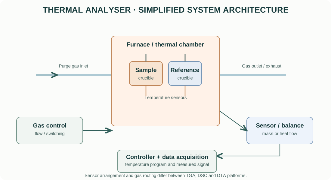
A typical thermal-analysis system includes a furnace, specimen and reference holders, temperature sensors, a controlled atmosphere, gas-flow system, balance or heat-flow sensor, controller and acquisition electronics.
Furnace and temperature control
The furnace follows a programmed temperature profile. Heating rate, cooling rate, isothermal holds and maximum temperature must be selected based on the material and research question.
The programmed temperature is not necessarily identical to the instantaneous specimen temperature. Thermal lag depends on sample mass, crucible, gas flow, heating rate, thermal contact and instrument design.
Temperature sensors
Thermocouples or other temperature sensors monitor the furnace, sample and reference positions depending on the instrument. Calibration and sensor placement affect temperature accuracy.
Balance and mass measurement in TGA
A TGA uses a sensitive balance arrangement to detect small mass changes while the specimen is heated. Buoyancy changes, gas density, convection, baseline drift, vibration and crucible effects can influence the measured mass.
Heat-flow measurement in DSC
In heat-flux DSC, the sample and reference are placed on a sensor platform and heat-flow differences are inferred from a calibrated thermal resistance and temperature difference. In power-compensation DSC, separate heaters maintain the sample and reference at a controlled temperature relationship, and the differential power is measured.
Atmosphere and gas control
The specimen environment may be inert, oxidizing, reducing, reactive or vacuum, depending on the instrument. Gas purity, flow rate, pressure and switching transients can influence results.
Use only gases and operating conditions approved for the instrument. Reactive or toxic off-gases require suitable exhaust and safety controls.
3. Interpreting a TGA curve
A TGA curve is often normalized to initial mass:
[ m_{rel}(T)=% ]
The mass change over a selected interval is:
[ m(%)=% ]
where (m_i) and (m_f) are the mass at the beginning and end of the interval.
A TGA step can indicate mass loss or gain, but the chemical identity of the evolved species is not established by TGA alone. Couple TGA with evolved-gas analysis such as FTIR or mass spectrometry when the gas identity is important.
DTG
The derivative curve highlights the temperature of maximum mass-change rate. A DTG peak may represent overlapping reactions, and peak position depends on heating rate and sample conditions.
Do not equate the DTG peak temperature with a unique decomposition temperature unless the operational definition is stated.
4. Interpreting DSC and DTA signals
Thermal events can appear as peaks, steps or changes in baseline.
| Event | Common signal behaviour | Additional evidence |
|---|---|---|
| Melting | Endothermic DSC/DTA event | Reheating, XRD before/after, phase diagram |
| Crystallization | Exothermic event | XRD or microscopy after thermal treatment |
| Glass transition | Baseline / heat-capacity step in DSC | Modulated DSC or complementary analysis |
| Dehydration | Often endothermic; may also cause mass loss | TGA and evolved-gas analysis |
| Oxidation | Often exothermic and may cause mass gain | TGA under controlled atmosphere |
| Decomposition | May be endothermic or exothermic; often mass loss | TGA-MS / TGA-FTIR |
| Solid–solid transition | Endothermic or exothermic event | Variable-temperature XRD |
Peak direction depends on the instrument convention. Record whether exothermic events are plotted upward or downward.
5. Enthalpy and heat capacity from DSC
When a calibrated DSC heat-flow signal is integrated over a thermal event, the heat associated with the event can be estimated. For a mass-normalized enthalpy:
[ H=_{t_1}^{t_2}q(t),dt ]
where (q) is the heat-flow rate and (m) is the sample mass. The result depends on baseline selection, calibration, integration limits and instrument convention.
Heat capacity can be estimated from the heat-flow response under a known heating rate, with suitable calibration and correction:
[ C_p ]
where (=dT/dt) is the heating rate and (m) is the sample mass. This simplified relationship assumes a suitable baseline and that the measured heat flow represents the sample heat capacity under the method conditions.
6. Why heating rate matters
Heating rate changes thermal lag and the apparent temperature of a thermal event. Faster heating often shifts a peak to higher temperature because the specimen has less time to equilibrate and reaction kinetics are sampled differently.
Heating rate also affects: - separation of overlapping events; - peak height and width; - reaction conversion at a given temperature; - baseline stability and signal-to-noise ratio; - total measurement time.
For kinetic analysis, collect data at multiple heating rates using a validated method. Do not infer activation energy from one heating ramp alone.
7. Crucibles, sample mass and packing
Crucible material and geometry must be compatible with the sample, atmosphere and temperature range. Common materials include alumina, platinum, aluminium and other specialized alloys or ceramics.
Consider: - chemical reaction between specimen and crucible; - melting or softening of the crucible; - catalytic effects of the crucible material; - sample spreading, packing and contact; - crucible lid and vent geometry; - maximum safe sample mass and pressure from evolved gases.
Use a consistent specimen mass and geometry for comparative studies. Excessive sample mass can cause temperature gradients and broaden or distort thermal events.
8. Atmosphere, gas flow and buoyancy
Atmosphere can change the reaction pathway. A material may decompose differently in nitrogen, argon, air, oxygen, hydrogen-containing gas or vacuum.
In TGA, changing gas density with temperature can produce a buoyancy-related baseline shift. Gas-flow changes can also create transients. Blank runs and appropriate baseline correction are important.
Record: - gas identity and purity; - flow rate; - pressure or purge conditions; - switching sequence and stabilization time; - exhaust and off-gas handling.
Never use a reducing or reactive gas without approved system configuration and safety controls.
9. Calibration and validation
Thermal analysers require calibration and verification appropriate to the measured quantity.
Temperature calibration
Use certified transition standards with known melting or transition temperatures under the instrument’s calibration procedure. Calibration can depend on heating rate, crucible and sensor configuration.
Mass calibration and baseline
For TGA, verify balance calibration and baseline stability using the instrument’s recommended procedure. Empty-crucible runs help identify drift and buoyancy effects.
DSC heat-flow calibration
Use certified enthalpy standards and the appropriate calibration protocol. Verify baseline and temperature calibration under conditions similar to the measurement.
DTA calibration
DTA temperature and signal calibration depend on the instrument design. Do not assume that a DTA peak area is directly quantitative without a validated calibration relationship.
10. Practical workflow for ceramic powders and oxide precursors
- Define the question: water content, precursor decomposition, carbonate removal, oxidation state change, phase-transition temperature or thermal stability.
- Select TGA, DSC, DTA or a coupled technique based on the expected signal.
- Confirm specimen compatibility with crucible, atmosphere and maximum temperature.
- Choose a representative sample mass and particle condition.
- Run an empty-crucible or baseline measurement as required.
- Select heating rate, gas type, flow and temperature range.
- Inspect raw data for baseline drift, buoyancy, sudden gas-flow artefacts and instrument limits.
- Compare thermal events with XRD, FTIR, MS or other complementary evidence.
- Report the operational definition used for onset, peak and completion temperatures.
- Preserve raw data and all acquisition parameters.
11. Common errors and artefacts
| Problem | Effect | Control |
|---|---|---|
| Excessive sample mass | Thermal gradients and broadened events | Reduce mass and improve reproducibility |
| Poor crucible contact | Delayed or distorted thermal response | Use suitable crucible and consistent loading |
| Baseline drift | Incorrect mass or heat-flow change | Blank run and validated correction |
| Buoyancy / convection | Apparent mass change in TGA | Use matched blank and stable gas flow |
| Heating-rate mismatch | Shifted event temperatures | Compare only under stated, controlled rates |
| Gas contamination | Unexpected oxidation or decomposition | Verify gas purity and line integrity |
| Crucible reaction | Artificial event or mass change | Select chemically compatible crucible |
| Overlapping reactions | Ambiguous peaks or steps | Use slower/multiple ramps and coupled analysis |
| Unspecified peak convention | Incorrect endothermic/exothermic assignment | State instrument plotting convention |
12. Choosing between TGA, DSC and DTA
| Research question | Preferred measurement | Why |
|---|---|---|
| How much mass is lost during precursor decomposition? | TGA / DTG | Direct mass-change measurement |
| At what temperature does a phase transition occur? | DSC or DTA | Thermal event detection |
| What is the enthalpy of melting or reaction? | DSC | Calibrated heat-flow integration |
| Does oxidation cause mass gain? | TGA in controlled atmosphere | Tracks mass change |
| Which gas evolves during decomposition? | TGA-MS or TGA-FTIR | Adds evolved-gas identification |
| Is a thermal event associated with a crystal-structure change? | DSC/DTA plus variable-temperature XRD | Connects thermal signal with structural change |
13. Manufacturer resources
Official manufacturer resources:
- TA Instruments — Thermal Analysis
- NETZSCH — Thermal Analysis
- Mettler Toledo — Thermal Analysis
- Hitachi High-Tech — Thermal Analysis
Compare temperature range, atmosphere capability, balance sensitivity, DSC heat-flow range, sensor design, cooling accessories, coupled gas analysis, autosampler and software. Confirm the exact instrument configuration and accessories installed in the laboratory.
14. Reporting checklist
A reproducible thermal-analysis method should report:
- instrument manufacturer and model;
- technique (TGA, DTG, DSC or DTA);
- sample mass and preparation;
- crucible material, geometry and lid condition;
- temperature range and heating/cooling rate;
- atmosphere, gas purity, flow and pressure;
- calibration standards and baseline procedure;
- replicate measurements;
- onset, peak and endset definitions;
- DSC integration baseline and enthalpy normalization;
- instrument convention for endothermic/exothermic direction;
- software and data-processing method.
15. Intellectual-property and educational scope
The explanatory text and figures are original educational material. The diagrams are conceptual and are not copied from manufacturer manuals or product brochures. Manufacturer names and links identify their respective products. Product photographs, manuals, proprietary schematics and trademarks remain the property of their owners.
This guide explains general thermal-analysis principles. It does not replace instrument-specific training, gas-system safety procedures, crucible compatibility review or the current operating manual.