Thermocouples: Seebeck Effect, Reference Junctions and Temperature Measurement
Thermocouples and Temperature Measurement
LABORATORY MEASUREMENT SYSTEMS · TOPIC 04.02 · FOUNDATIONAL LEVEL
A thermocouple is a temperature sensor made from two dissimilar electrical conductors joined to form a measuring junction. A temperature difference between this junction and the reference junction produces a thermoelectric electromotive force (EMF). The instrument measures that voltage and uses a calibrated thermocouple relationship to infer temperature.
A thermocouple does not directly measure absolute temperature. It produces a voltage related to the temperature difference between two junction regions. Correct reference-junction compensation is therefore essential.
1. Physical principle: the Seebeck effect
When a temperature gradient exists along a conductor, charge carriers redistribute and an electric field develops. In a thermocouple circuit made from two different materials, the net thermoelectric response depends on their relative Seebeck coefficients.
For a thermocouple pair A and B, the open-circuit EMF can be expressed as:
[ E_{AB}(T_h,T_c)=_{T_c}^{T_h}[S_A(T)-S_B(T)],dT ]
where (T_h) is the measuring-junction temperature, (T_c) is the reference-junction temperature, and (S_A) and (S_B) are the temperature-dependent Seebeck coefficients of the two conductors.
For a narrow temperature interval, a simplified approximation is:
[ E_{AB}(S_A-S_B)(T_h-T_c) ]
The real voltage–temperature relationship is nonlinear over a wide temperature range. Standardized reference functions and tables—not one constant sensitivity—are used for accurate conversion.
2. Thermocouple measurement chain
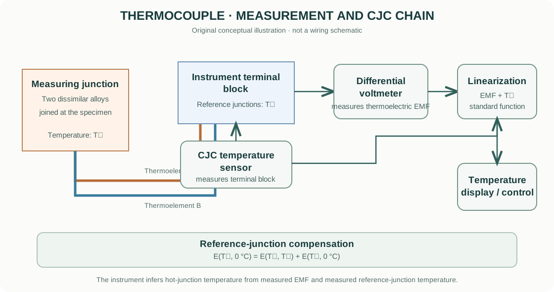
- Measuring junction: the two thermoelements are joined at the point whose temperature is to be measured.
- Thermocouple extension wires: wires of the correct thermocouple or compatible extension grade carry the signal toward the instrument. Incorrect wire or connectors can introduce additional thermoelectric junctions.
- Reference junction: the transition from thermocouple alloys to the instrument’s copper terminals occurs at a measurable temperature.
- Reference-junction sensor: the instrument estimates the terminal-block temperature using an internal sensor or an external reference arrangement.
- Low-level voltage measurement: a high-input-impedance differential circuit measures the thermoelectric EMF, which is commonly in the microvolt-to-millivolt range.
- Linearization and conversion: the instrument combines the measured EMF with the reference-junction temperature and applies the relevant standardized thermocouple function.
- Display / controller: the calculated temperature is displayed, logged or used by a control algorithm.
3. Why reference-junction compensation is required
Thermocouple reference tables are conventionally defined relative to a reference junction at 0 °C. In practical instruments, the terminal block is rarely maintained at exactly 0 °C. The instrument therefore measures the terminal-block temperature and calculates the equivalent EMF associated with that reference temperature.
Conceptually:
[ E(T_h,0)=E(T_h,T_c)+E(T_c,0) ]
The instrument uses this compensated EMF to determine the measuring-junction temperature. This is commonly called cold-junction compensation (CJC) or reference-junction compensation.
CJC is not a correction for a poor sensor attachment or an incorrect thermocouple wire. It compensates for the reference-junction temperature under the assumed wiring and sensor arrangement.
4. Common thermocouple types
| Type | Positive / negative alloys (common designation) | Typical characteristics |
|---|---|---|
| K | Chromel / Alumel | General-purpose, broad useful temperature range, widely used in furnaces |
| J | Iron / Constantan | Common industrial type; iron leg can oxidize in some environments |
| T | Copper / Constantan | Useful for lower-temperature work and stable measurements |
| E | Chromel / Constantan | Relatively high sensitivity among common base-metal types |
| N | Nicrosil / Nisil | Designed for improved stability in some high-temperature environments |
| R / S | Platinum–rhodium alloys | Noble-metal types for high-temperature measurement; lower output and higher cost |
The usable temperature range depends on wire diameter, insulation, sheath, atmosphere, drift limits and applicable standard. Do not select a type from a temperature-range table alone.
5. Reading and interpreting the signal
Thermocouple output is small. The measurement system must therefore manage:
- Input offset and bias current: can be significant relative to a small thermoelectric signal.
- Electrical noise: mains pickup, ground loops and electromagnetic interference can corrupt the voltage.
- Thermal gradients at connectors: unintended junctions can create additional EMFs.
- Polarity: reversing the thermocouple leads reverses the measured voltage relative to the reference.
- Common-mode voltage: grounded heaters or specimens can place the sensor circuit at a potential that exceeds the input limits of an unsuitable instrument.
For low-level or differential temperature measurements, use appropriate isolated or differential inputs, correct extension wire, stable connectors and a well-defined grounding arrangement.
6. Installation and practical measurement
- Select the thermocouple type, sheath material, diameter and insulation for the temperature, atmosphere and response-time requirement.
- Confirm that the readout or controller is configured for the same thermocouple type.
- Use matching thermocouple connectors and the correct extension/compensating cable. Respect polarity throughout the circuit.
- Place the measuring junction where it represents the temperature of interest. Avoid measuring a furnace-wall temperature when the specimen temperature is required.
- Ensure suitable thermal contact and immersion depth. A large sheath or poor contact can slow response and create conduction errors.
- Check the reference-junction compensation method and keep the instrument terminals away from strong temperature gradients.
- Allow the sensor, specimen and furnace to reach thermal equilibrium when the experiment requires a steady-state temperature.
- Record thermocouple type, wire/sheath construction, junction location, controller/readout model, CJC method, calibration status and acquisition interval.
7. Thermocouple versus RTD
A thermocouple and a resistance temperature detector (RTD) do not rely on the same physical principle.
| Feature | Thermocouple | RTD |
|---|---|---|
| Primary effect | Thermoelectric EMF | Temperature-dependent electrical resistance |
| Excitation | Self-generating voltage | Requires measurement current |
| Reference requirement | Reference-junction compensation | No thermocouple reference junction |
| Wiring | Correct thermocouple/extension alloys are essential | 2-, 3- or 4-wire resistance measurement |
| Typical strengths | Broad temperature coverage, rugged probes, fast response options | Stability, accuracy and repeatability over specified ranges |
| Main concerns | CJC, drift, inhomogeneity, parasitic EMFs | Lead resistance, self-heating, insulation and excitation current |
Neither sensor is universally superior. Selection depends on the required temperature range, uncertainty, response time, environment and calibration strategy.
8. Temperature controllers: measurement is not control
A temperature controller receives a sensor signal, converts it to a process temperature, compares it with a setpoint and adjusts a heater or cooling actuator. A common proportional–integral–derivative (PID) controller calculates a control output from the error:
[ e(t)=T_{set}(t)-T_{meas}(t) ]
[ u(t)=K_Pe(t)+K_Ie(t)dt+K_D ]
The PID output may control a solid-state relay, power controller or other actuator. The sensor measures temperature; the controller computes a corrective action; the power stage drives the heater. Sensor placement, thermal lag, furnace mass, heater geometry and tuning determine the actual temperature profile.
A controller display is not automatically the specimen temperature. For ceramic synthesis and sintering, specimen position, furnace uniformity, thermocouple placement and calibration can all matter.
9. Calibration, verification and uncertainty
Calibration compares the sensor/readout system with a traceable temperature reference over the intended range. A useful calibration may include the thermocouple, extension cable, connectors and readout as a complete measurement chain.
Potential uncertainty contributors include:
- thermocouple tolerance class and calibration uncertainty;
- reference-junction sensor accuracy and terminal-block gradients;
- thermoelectric inhomogeneity and wire ageing;
- immersion depth, conduction along the sheath and thermal contact;
- response lag during heating or cooling;
- electrical noise and parasitic thermal EMFs;
- furnace non-uniformity and specimen-to-sensor temperature difference.
For demanding work, calibrate or verify the complete chain at representative temperatures and document the uncertainty. A controller’s setpoint accuracy is not equivalent to the uncertainty of the specimen temperature.
10. Commercial examples and manufacturer resources
These are official product-family or product-information pages. They are included to help identify real sensor, readout and reference-junction hardware; they are not endorsements.
- OMEGA Engineering — Temperature products: thermocouples, probes, wire, connectors, reference junction products and temperature controllers.
- OMEGA — TRP thermocouple reference probes: examples of reference probes used in thermocouple calibration arrangements.
- Yokogawa Test & Measurement — Digital thermometers: examples of thermocouple-compatible handheld readout instruments, including TX10 series.
- Fluke — Temperature measurement instruments: manufacturer product and application information; confirm the specific thermometer and probe compatibility before use.
Use the current datasheet for the exact probe and readout. Check thermocouple type, temperature range, tolerance class, sheath and insulation limits, response time, CJC method, input isolation and calibration conditions.
11. Intellectual-property and educational scope
The explanatory text and functional diagram are original educational material. The diagram is a generalized measurement-chain illustration, not a reproduction of a manufacturer’s wiring diagram. Manufacturer names and product links identify their respective products; trademarks, product images, manuals and specifications remain the property of their owners. Consult official documentation for model-specific installation, safety and performance limits.
This guide describes general measurement principles. It does not replace the applicable thermocouple standard, manufacturer manual, calibration procedure or laboratory safety assessment.