Source Measure Unit (SMU): Four-Quadrant Source and Measurement
Source Measure Unit (SMU)
LABORATORY MEASUREMENT SYSTEMS · TOPIC 04.04 · SOURCE + MEASURE
A Source Measure Unit (SMU) combines a programmable electrical source with a precision measurement instrument. It can force a voltage and measure the resulting current, or force a current and measure the resulting voltage. Many SMUs can also operate in all four voltage-current quadrants, allowing them to source power to a device or sink power from it.
Central idea: an SMU is not simply a power supply connected to a multimeter. Its control loop, measurement path, output protection, compliance limits and timing are designed to coordinate electrical excitation and measurement.
1. What does an SMU do?
Common operating modes include:
- Voltage source, current measure (VSIM): apply a programmed voltage and measure the current response.
- Current source, voltage measure (ISVM): force a programmed current and measure the voltage response.
- Voltage sweep: step or ramp voltage and record current to obtain an I–V curve.
- Current sweep: step or ramp current and record voltage.
- Pulsed sourcing: apply short electrical pulses to reduce average heating or investigate transient behaviour, if supported by the model.
Typical applications include semiconductor and diode characterization, resistive materials, thin films, conductive oxides, sensors, electrochemical components within suitable voltage/current ranges, and leakage measurements.
2. Functional architecture and signal path
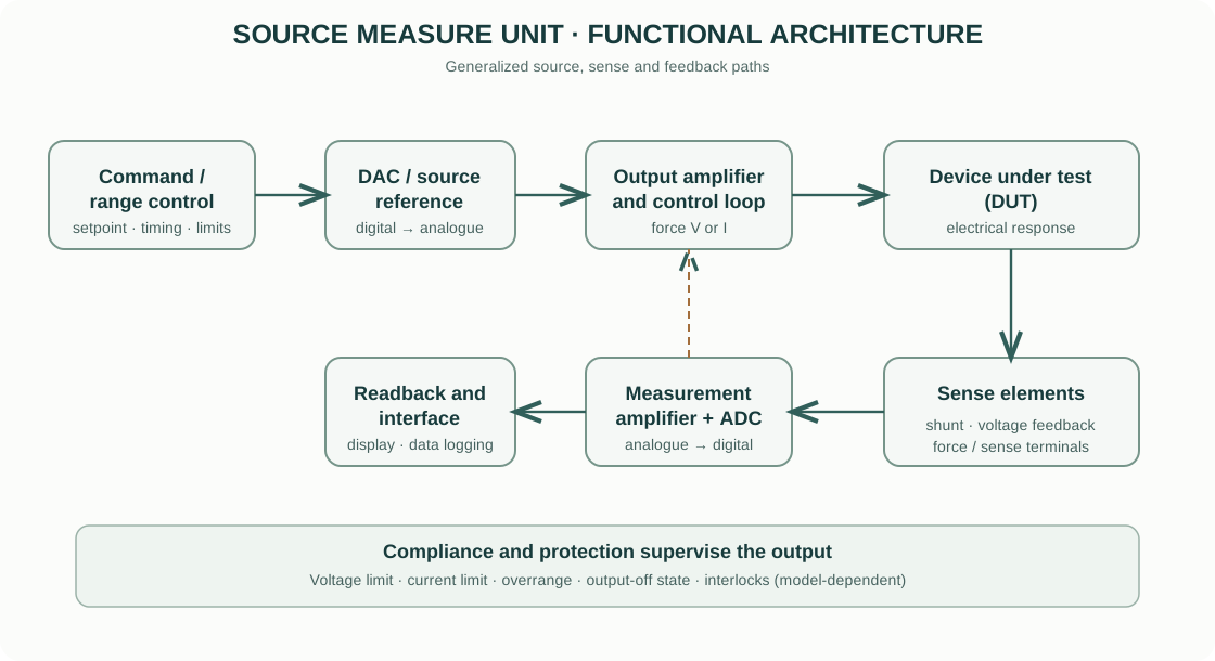
- Command and range control: the user or computer defines source function, level, range, timing and compliance.
- Source reference and DAC: a digital-to-analogue converter and reference generate the programmed output setpoint.
- Output amplifier / current control: a feedback stage drives the device under test (DUT) to establish the requested voltage or current.
- Sense element: a calibrated shunt or feedback network measures output current or voltage.
- Measurement amplifier and ADC: the sensed signal is conditioned and digitized.
- Feedback and protection: control circuitry regulates the output and monitors compliance, overrange and instrument limits.
- Readback and interface: measured values and status are returned to the display or computer.
This is a generalized architecture. The actual topology, number of ADCs, source ranges, isolation and feedback arrangement depend on the manufacturer and model.
3. Voltage-source mode
In voltage-source mode, the SMU regulates the DUT terminal voltage to the programmed value while measuring current.
For a simple resistive DUT:
[ I= ]
If the resistance is small, the required current can become large. The SMU must therefore be configured with a suitable current range and a safe current-compliance limit.
The voltage measured at the instrument terminals may differ from the voltage at the DUT if lead resistance, contact resistance or cable drops are significant. Four-wire remote sensing (when available) helps regulate or measure voltage at the DUT terminals rather than at the instrument output terminals.
4. Current-source mode
In current-source mode, the SMU forces a programmed current and measures the voltage developed across the DUT:
[ V_{DUT}=I_{force}R_{DUT} ]
The source must have sufficient voltage capability to drive the requested current through the DUT. The maximum available voltage is often described as the source voltage limit or compliance voltage.
If the DUT requires more voltage than the SMU can provide, the instrument cannot maintain the programmed current. The source enters a limit condition and the actual output must be interpreted from the status and measured readback.
5. Compliance: a critical protection setting
Compliance limits the output when the DUT response would exceed a configured voltage or current boundary. It is a protection and operating constraint, not a guarantee that the DUT is safe under every transient or fault condition.
- In voltage-source mode, current compliance limits the current delivered to the DUT.
- In current-source mode, voltage compliance limits the voltage developed across the DUT.
If compliance is reached, the programmed source value may no longer be maintained. The instrument may report a compliance status, and the measured value may reflect the limiting condition rather than the intended setpoint.
Always choose compliance based on the DUT ratings, wiring, thermal limits and expected behaviour. Start conservatively when the DUT characteristics are unknown.
6. Four-quadrant operation
The voltage-current plane is divided into four quadrants according to the signs of voltage and current. Sign conventions should be checked in the specific SMU manual, but the common convention is:
| Quadrant | Voltage | Current | Power (P=VI) | Typical behaviour |
|---|---|---|---|---|
| I | + | + | + | Source power |
| II | + | − | − | Sink power |
| III | − | − | + | Source power |
| IV | − | + | − | Sink power |
A four-quadrant SMU can source and sink power in both voltage polarities within its specified operating envelope. Not every SMU supports four-quadrant operation, and power/current limits may differ between quadrants.
7. Two-wire and four-wire connections
In a two-wire connection, the same pair of leads carries source current and senses voltage. Lead and contact resistance contribute to the measured voltage:
[ V_{meas}=V_{DUT}+I(R_{lead}+R_{contact}) ]
For low-resistance devices, this error can be significant. In a four-wire (Kelvin) connection, one pair forces current and a separate high-impedance pair senses the DUT voltage. This reduces the influence of force-lead resistance, provided the sense leads are connected at the correct DUT terminals.
Remote sense is not a substitute for correct contact placement or safe wiring. Long cables, unstable contacts and poor guarding can still introduce errors.
8. Guarding, shielding and low-current measurements
At low current, leakage through cable insulation, fixtures, humidity and contaminated surfaces can be comparable to the DUT current. Guarding uses a driven conductor maintained near the potential of the sensitive input node to reduce leakage across insulating surfaces. Shielding helps reduce capacitive pickup and electromagnetic interference.
For low-current measurements: - use suitable low-noise triaxial or guarded cabling when supported; - keep insulators clean and dry; - minimize cable movement and triboelectric effects; - allow settling after range changes or voltage steps; - use an appropriate integration time and measurement range; - follow the manufacturer’s guarding and grounding arrangement.
9. Building an I–V curve
A basic voltage-sweep measurement consists of applying a sequence of voltage setpoints and recording current at each point.
[ (V_1,I_1),(V_2,I_2),,(V_n,I_n) ]
The resulting I–V curve can reveal ohmic behaviour, rectification, leakage, threshold behaviour, hysteresis or breakdown-like transitions. The interpretation depends on device physics and measurement conditions.
A reproducible sweep must specify: - start and stop voltage, step size and sweep direction; - current compliance and voltage limits; - source delay / settling time; - integration time and measurement aperture; - sweep rate and number of cycles; - two-wire or four-wire connection; - DUT temperature, illumination, atmosphere and preconditioning where relevant.
For hysteretic devices, measure forward and reverse sweeps and report the sweep protocol. A single I–V trace is not enough to establish stability or reproducibility.
10. Practical measurement workflow
- Read the SMU and fixture ratings before connecting the DUT.
- Identify the DUT terminals and expected electrical range.
- Choose source mode: voltage force/current measure or current force/voltage measure.
- Select source and measurement ranges; use auto-ranging only when its timing and settling behaviour are acceptable.
- Set conservative compliance limits and output-off state.
- Connect force and sense leads correctly. Use Kelvin connections when lead resistance matters.
- Configure integration time, delay, sweep points and trigger behaviour.
- Enable output only after verifying the wiring and settings.
- Monitor compliance, overrange and unexpected current or voltage.
- Save raw data, settings, instrument model, wiring diagram and environmental conditions.
11. Common errors and limitations
| Error source | Consequence | Control |
|---|---|---|
| Incorrect compliance | DUT damage or unintended limiting | Set conservative limits based on DUT ratings |
| Lead resistance | Incorrect DUT voltage or resistance | Use remote sense / Kelvin wiring |
| Insulation leakage | False current, especially at low levels | Clean fixtures, guard and shield |
| Settling transient | Readings depend on acquisition delay | Allow settling and document timing |
| Self-heating | DUT changes during sweep | Reduce power, use pulsed mode or monitor temperature |
| Range changes | Measurement discontinuity or delay | Fix ranges where appropriate and inspect transitions |
| Ground loops | Offset, noise or unsafe current paths | Follow instrument grounding and isolation requirements |
| Compliance reached | Programmed source is not maintained | Check compliance status and measured readback |
12. Commercial SMU examples
Official manufacturer resources for instrument families and technical documentation:
- Keithley — Source Measure Units: SMU families, application information and manuals.
- Keysight — Source Measure Units: precision source/measurement instruments and semiconductor test applications.
- Yokogawa Test & Measurement: source and measurement instrument product information.
Compare source/measurement ranges, resolution, accuracy, maximum voltage/current/power, four-quadrant capability, pulse performance, remote sensing, guarding, isolation, measurement speed and supported interfaces. The exact datasheet and user manual take precedence over a family-level product page.
13. Intellectual-property and educational scope
The explanatory text and functional architecture diagram are original educational material. The diagram is a generalized conceptual representation, not a reproduction of a proprietary instrument schematic. Manufacturer names and links identify their respective products; trademarks, manuals, specifications and product images remain the property of their owners.
This guide explains general SMU principles. It does not replace the exact instrument manual, DUT ratings, electrical-safety training or laboratory risk assessment.