Pressure Transducers: Sensor Physics, Signal Conditioning and Calibration
Pressure Transducers
LABORATORY MEASUREMENT SYSTEMS · TOPIC 04.06 · PRESSURE MEASUREMENT
A pressure transducer converts pressure into an electrical output. The sensing element responds to mechanical stress, diaphragm displacement or another pressure-dependent effect; the instrument conditions this response and produces a voltage, current or digital signal.
A pressure transducer is not necessarily a complete pressure gauge or controller. It may require an excitation supply, signal conditioner, amplifier, display or data-acquisition system.
Central idea: the reading depends on the pressure reference, sensor technology, installation, excitation, calibration and the dynamic response of the complete measurement chain.
1. What is pressure?
Pressure is force per unit area:
[ p= ]
The SI unit is the pascal (Pa), equal to one newton per square metre. Common laboratory and industrial units include kPa, MPa, bar, mbar and psi.
Pressure must always be interpreted relative to a reference:
- Absolute pressure: referenced to a vacuum.
- Gauge pressure: referenced to local atmospheric pressure.
- Differential pressure: the difference between two applied pressures.
For gauge pressure:
[ p_{gauge}=p_{absolute}-p_{atmospheric} ]
A reading of zero gauge pressure does not mean zero absolute pressure; it means the measured pressure is approximately equal to local atmospheric pressure.
2. Functional measurement chain
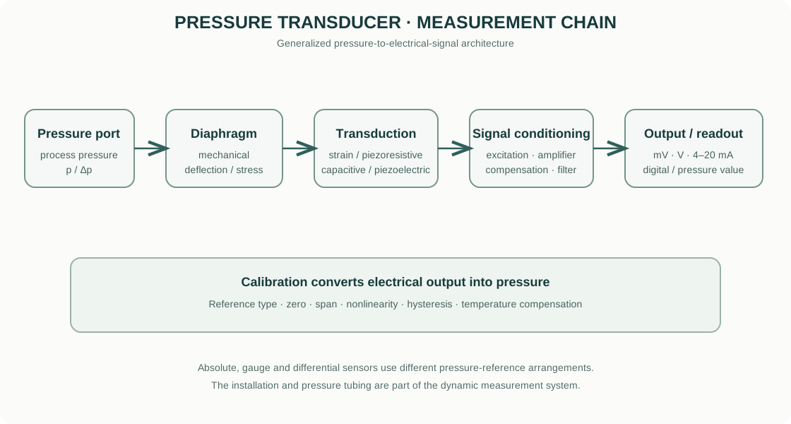
- Pressure port and isolation: process pressure is transferred to the sensing element through a port, diaphragm or pressure interface.
- Mechanical sensing element: pressure deforms a diaphragm or other structure.
- Transduction element: strain gauges, piezoresistors, capacitive plates or a piezoelectric material convert the mechanical response into an electrical change.
- Excitation and signal conditioning: bridge excitation, amplification, temperature compensation and filtering prepare the signal.
- Output stage: the sensor provides a specified voltage, current-loop or digital output.
- Display / acquisition: a calibrated receiver converts the electrical output into pressure units and records the value.
The exact architecture depends on the sensor technology and output type. The diagram is conceptual rather than a model-specific circuit.
3. Sensor technologies
3.1 Strain-gauge pressure transducers
Pressure deflects a diaphragm. Bonded or deposited strain gauges experience tensile or compressive strain, changing their electrical resistance. Gauges are often connected in a Wheatstone bridge to convert small resistance changes into a differential voltage.
The bridge output is related to strain and therefore to diaphragm stress and pressure. Temperature compensation and calibration are needed because gauge resistance, elastic properties and bridge components can vary with temperature.
3.2 Piezoresistive pressure sensors
In a piezoresistive sensor, mechanical stress changes the resistivity of a semiconductor element. Piezoresistors are commonly arranged in a bridge on or near a diaphragm. These sensors can provide high sensitivity, but their response and offset may be temperature-dependent.
3.3 Capacitive pressure sensors
A diaphragm and a fixed electrode form a capacitor. Pressure-induced diaphragm displacement changes the electrode spacing and therefore the capacitance:
[ C= ]
where ε is permittivity, (A) is effective electrode area and (d) is separation. The capacitance change is measured by an electronic circuit and converted to pressure.
Capacitive sensors can be useful for low-pressure and differential-pressure measurements, but parasitic capacitance, contamination and mechanical overload must be considered.
3.4 Piezoelectric pressure sensors
A piezoelectric material generates electrical charge when mechanically stressed. These sensors are particularly useful for dynamic or rapidly changing pressure. Because charge can leak through finite insulation resistance and the measurement electronics, conventional piezoelectric pressure sensors are generally not suitable for indefinitely stable static-pressure measurement without a specialized charge-measurement arrangement.
4. Static and dynamic response
A pressure sensor has a finite response time and frequency response. For a step change in pressure, the output may rise gradually, overshoot or oscillate depending on the mechanical structure, damping, fluid path and electronics.
For dynamic measurements, consider: - sensor natural frequency and resonance; - damping and overshoot; - pressure-line length and internal volume; - gas compressibility or liquid-filled line effects; - sampling rate and signal-conditioning bandwidth.
A long narrow tube can attenuate or delay pressure transients. The sensor may be fast while the installed pressure line is not.
5. Electrical output types
Common output arrangements include:
- Millivolt bridge output: requires a suitable regulated excitation and low-noise differential amplifier.
- Voltage output: for example, a specified 0–5 V or 0–10 V range; check output impedance and supply requirements.
- Current loop: often 4–20 mA in industrial installations. The receiver converts current to a voltage across a known resistor or uses a current-input module.
- Digital output: may use a fieldbus or serial protocol; scaling, units and diagnostic status must be configured.
Do not assume a sensor’s output range from its connector or cable colours. Use the exact datasheet pinout, supply range and wiring instructions.
6. Calibration and scaling
A common linear output relationship is:
[ y=y_0+S(p-p_0) ]
where (y) is electrical output, (y_0) is the output at reference pressure (p_0), and (S) is sensitivity. The receiver inverts this relationship to calculate pressure:
[ p=p_0+ ]
Real sensors may require offset, span, nonlinearity, hysteresis and temperature corrections. Calibration should use a traceable pressure reference over the intended operating range and should include the signal conditioner or readout where possible.
7. Installation and practical workflow
- Identify whether the application needs absolute, gauge or differential pressure.
- Check the pressure range, proof pressure, burst pressure and overload limits.
- Confirm wetted-material compatibility with the gas or liquid, including seals and diaphragm material.
- Check port size, thread standard, sealing method and mounting orientation.
- Install with suitable isolation valves and pressure-rated fittings.
- Wire the sensor using the specified excitation, polarity, shielding and grounding arrangement.
- Configure the receiver for the correct output range and engineering units.
- Zero or tare only under the pressure condition specified by the manufacturer.
- Apply known reference pressures and verify zero, span and intermediate points when required.
- Record pressure reference, sensor range, output type, excitation, calibration data, temperature and installation details.
Never exceed the rated pressure, proof pressure or temperature. Depressurize and isolate the system before removing a sensor or fitting. Use fittings and tubing rated for the gas, liquid and maximum possible pressure.
8. Common sources of error
| Error source | Mechanism | Control |
|---|---|---|
| Wrong pressure reference | Gauge and absolute readings are confused | Label reference type and units |
| Zero offset | Sensor or receiver offset shifts all readings | Zero under the correct reference condition |
| Temperature drift | Sensor bridge and mechanical properties change | Use compensation and calibrate at relevant temperatures |
| Hysteresis | Output differs depending on increasing or decreasing pressure | Characterize both directions if important |
| Overpressure | Diaphragm or sensing element is permanently damaged | Respect operating, proof and burst ratings |
| Pressure-line dynamics | Tubing delays or attenuates transients | Minimize line length and characterize installation |
| Electrical noise | Small bridge signals are corrupted | Shielding, differential input and proper grounding |
| Incorrect scaling | Output is converted using the wrong span or units | Verify receiver configuration against datasheet |
| Fluid compatibility | Corrosion, swelling or contamination alters the sensor | Select compatible wetted materials |
9. Commercial pressure-sensor examples
Official manufacturer resources:
- WIKA — Pressure sensors: pressure transmitters and sensors for industrial and laboratory applications.
- Keller Pressure — Pressure transmitters: piezoresistive pressure measurement products and technical information.
- OMEGA Engineering — Pressure measurement: pressure transducers, transmitters and accessories.
- Honeywell — Pressure sensors: pressure sensor product families and technical resources.
Compare pressure reference, range, accuracy, stability, output type, supply voltage, response time, overload rating, wetted materials, temperature compensation, electrical connection and calibration certificate. Use the datasheet for the exact model.
10. Intellectual-property and educational scope
The explanatory text and functional diagram are original educational material. The diagram is a generalized representation of a pressure measurement chain and does not reproduce a proprietary manufacturer schematic. Manufacturer names, trademarks and links identify their respective owners; product images, manuals and specifications remain their property.
This guide explains general pressure-transducer principles. It does not replace the exact sensor manual, pressure-system design review, calibration procedure or laboratory safety assessment.