Mass Flow Controller (MFC): Thermal Sensing, Gas Calibration and Flow Control
Mass Flow Controller (MFC)
LABORATORY MEASUREMENT SYSTEMS · TOPIC 04.05 · GAS FLOW CONTROL
A mass flow controller (MFC) measures and regulates the mass flow rate of a gas. It is widely used in controlled-atmosphere furnaces, chemical reactors, fuel-cell and electrolyzer test stations, sputtering systems and gas-mixing manifolds.
An MFC is different from a mass flow meter: a meter measures flow, whereas a controller combines a flow sensor with a control circuit and a valve to regulate flow toward a setpoint.
Central idea: the instrument measures a sensor response related to gas flow, converts that response using a gas- and calibration-dependent relationship, compares the measured flow with the setpoint, and adjusts a valve.
1. What is mass flow?
Mass flow rate is the mass of gas passing through a cross-section per unit time:
[ m= ]
Volumetric flow rate is volume per unit time:
[ Q= ]
The two quantities are related by gas density:
[ m=Q ]
Because gas density depends on pressure, temperature and composition, volumetric flow is meaningful only when its reference conditions are stated. Many gas instruments report standard or normalized volumetric flow (for example, sccm or slm), but the exact reference temperature and pressure must be checked in the instrument documentation.
2. Functional architecture
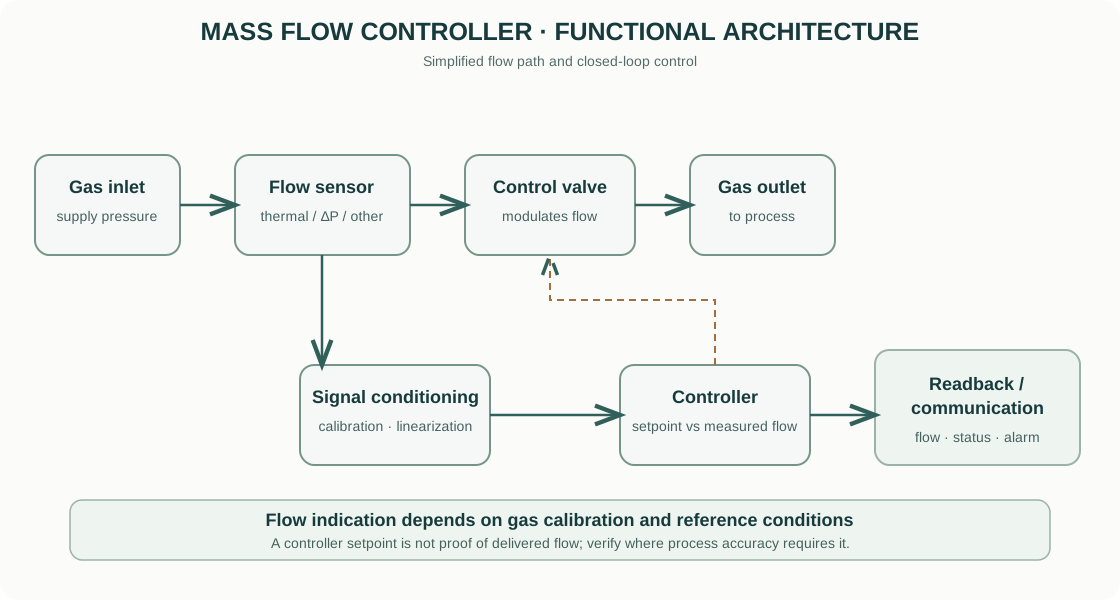
- Gas inlet and flow path: the gas enters through a defined body and internal flow channel.
- Flow sensor: a thermal, differential-pressure or other sensor generates a signal related to the flow rate.
- Signal conditioning: amplification, temperature compensation and calibration functions convert the sensor output into a flow estimate.
- Setpoint and controller: the electronics compare the measured flow with the requested setpoint.
- Control valve: a proportional valve changes the flow resistance to regulate the gas flow.
- Readback and communication: the instrument reports the measured flow and status to a display or host controller.
The sensing technology and valve architecture differ between MFC families. Not all MFCs use thermal sensing.
3. Thermal mass-flow sensing
A common MFC design uses a thermal sensor. A small fraction of the gas is routed through a sensor tube or bypass arrangement. A heater introduces thermal energy, and temperature sensors detect the resulting temperature distribution or heat transfer.
For a simplified heated sensor, the energy balance is related to the gas mass flow:
[ P_{heater}m c_pT + Q_{loss} ]
where (P_{heater}) is heater power, (c_p) is gas specific heat capacity, (Delta T) represents a characteristic gas temperature rise, and (Q_{loss}) includes heat losses to the sensor body and surroundings.
This is a conceptual energy balance, not a universal MFC calibration equation. Real thermal MFCs use a geometry-specific sensor response and calibration function. The response depends on gas thermal properties, sensor design, pressure and operating conditions.
4. Differential-pressure and other sensing approaches
Some flow controllers infer flow from a pressure difference across a defined restriction or flow element. For suitable flow regimes and geometries, the pressure drop is related to flow. The relationship depends on gas density, viscosity, compressibility, Reynolds number and the device geometry.
Other instruments use laminar flow elements, Coriolis principles or other technologies. The term “MFC” describes the control function, not one unique sensing principle. Always identify the sensing technology of the actual instrument.
5. Why gas type matters
A thermal MFC calibrated for nitrogen does not automatically measure every gas accurately when used with the same displayed setpoint. Gas thermal conductivity, heat capacity, viscosity and density affect the sensor response and flow behaviour.
Gas conversion factors are sometimes provided by manufacturers, but they are approximations tied to a specified instrument family, reference gas and operating conditions. They should not be treated as universal constants.
For mixed gases or unusual process conditions, use a calibration specifically suited to the mixture or a suitable independent flow-verification method. Check whether the controller supports a selectable gas table and whether the gas table applies to the exact model and firmware.
6. Control loop and valve operation
The controller compares the setpoint ẏset with the measured flow ẏmeas and forms an error:
[ e(t)=m_{set}(t)-m_{meas}(t) ]
A control algorithm adjusts the valve command to reduce the error. The valve may be proportional, solenoid-based or another design. Its available authority depends on upstream pressure, downstream pressure, valve characteristics and gas properties.
The MFC cannot regulate a requested flow if the pressure differential is insufficient or if the valve is outside its usable range. A setpoint is a requested condition, not proof that the gas flow has actually reached that value.
7. Pressure, range and reference conditions
An MFC is specified for a flow range and pressure operating window. Check: - maximum and minimum inlet pressure; - allowable outlet or back pressure; - required differential pressure; - maximum operating pressure and proof pressure; - gas compatibility and wetted materials; - reference temperature and pressure for volumetric display units; - turndown ratio and specified accuracy range.
A controller operating near the bottom of its full-scale range may have a larger relative uncertainty than one operating in its preferred range. Avoid assuming that accuracy is a constant percentage of the instantaneous reading.
8. Practical setup and verification
- Confirm the exact gas, purity, supply pressure and required flow range.
- Verify gas compatibility of the MFC body, seals, valve and connectors.
- Check the manufacturer’s specified inlet and outlet pressure window.
- Install the instrument in the correct flow direction and use leak-tested fittings.
- Purge the line using an approved procedure before introducing the process gas.
- Select the correct gas calibration or gas table for the exact model.
- Set a conservative initial flow and confirm that downstream equipment can accept it.
- Allow the sensor and gas line to stabilize, especially after a gas or temperature change.
- Compare the readback with an independent flow standard when the process requires traceable verification.
- Record gas identity, calibration basis, pressure, temperature, setpoint, readback, reference conditions and verification method.
Never use oxygen-service equipment with incompatible oils, grease, seals or contamination. Follow the gas supplier’s handling requirements and the MFC manufacturer’s safety instructions.
9. Common error sources
| Error source | Consequence | Control |
|---|---|---|
| Wrong gas calibration | Systematic flow error | Select correct gas table or obtain gas-specific calibration |
| Incorrect reference conditions | Reported sccm/slm is misinterpreted | Record reference temperature and pressure |
| Inadequate pressure differential | Flow cannot reach setpoint | Check pressure window and downstream restriction |
| Leaks | Actual delivered flow differs from indicated flow | Leak-test fittings and manifold |
| Contamination / particles | Sensor or valve response changes | Use specified filtration and clean gas handling |
| Condensation | Sensor response and flow path may be affected | Keep gas above dew point where required |
| Wrong flow direction | Incorrect operation or damage | Follow body arrows and manual |
| Poor range selection | High relative uncertainty at low flow | Select an appropriate full-scale range |
| Unverified gas factor | Incorrect conversion | Use manufacturer-supported data or calibration |
10. Commercial MFC examples
Official manufacturer resources:
- HORIBA — Mass Flow Controllers: mass flow controller families and application information.
- MKS Instruments — Mass Flow Controllers: thermal and other flow-control product families, documentation and application resources.
- Brooks Instrument — Mass Flow Controllers: gas flow controllers, sensor technology and product information.
- Alicat Scientific — Mass Flow Controllers: mass flow control instruments and product documentation.
Compare full-scale flow range, accuracy specification, repeatability, response time, gas calibration, pressure window, valve type, wetted materials, communication interface and calibration traceability. The exact model datasheet is essential.
11. Intellectual-property and educational scope
The explanatory text and functional diagram are original educational material. The diagram is a generalized representation and does not reproduce a proprietary manufacturer’s sensor or valve design. Manufacturer names, trademarks and product links identify their respective owners; product photographs, manuals and specifications remain their property.
This guide describes general MFC principles. It does not replace the exact model manual, gas compatibility assessment, pressure-system safety review or calibration procedure.