Potentiostat and Galvanostat: Operating Principles and Electrochemical Measurements
Potentiostat and Galvanostat
ELECTROCHEMICAL INSTRUMENTATION · TOPIC 02.01 · CONTROLLED ELECTROCHEMICAL MEASUREMENTS
A potentiostat is a feedback-controlled instrument that maintains the potential of a working electrode relative to a reference electrode while measuring the current flowing through the cell. A galvanostat instead controls the cell current and measures the resulting electrode potential. These are related operating modes, but they are not interchangeable descriptions of the same measurement.
The instrument does not measure an abstract electrochemical reaction directly. It controls electrical boundary conditions at the cell terminals and records the response of a real electrochemical system. Electrode geometry, reference-electrode placement, electrolyte resistance, cable layout, cell capacitance and instrument limits all influence the result.
1. The measurement question: what is controlled?
Potentiostatic operation
In potentiostatic mode, the instrument compares the measured working-electrode potential against a programmed command and adjusts the cell current to reduce the difference:
[ E_{WE-RE}(t) = E_{WE}(t)-E_{RE}(t) ]
The controlled quantity is the working-electrode potential relative to the reference electrode. The measured response is current, commonly reported as amperes or current density.
Typical applications include cyclic voltammetry (CV), linear sweep voltammetry (LSV), chronoamperometry (CA), potential-step experiments and controlled-potential electrolysis.
Galvanostatic operation
In galvanostatic mode, the instrument controls current and measures the resulting potential response. Typical applications include chronopotentiometry (CP), galvanostatic charge/discharge, electrodeposition at controlled current and electrochemical conditioning.
The potential may drift as the electrode surface, concentration profile, cell resistance or reaction mechanism changes. A voltage limit or compliance limit is therefore essential.
| Mode | Controlled variable | Measured response | Typical experiment |
|---|---|---|---|
| Potentiostatic | WE potential vs RE | Cell current | CV, LSV, CA |
| Galvanostatic | Cell current | Cell / electrode potential | CP, galvanostatic cycling |
2. Three-electrode cell: the essential arrangement
A conventional three-electrode configuration separates the potential-sensing function from the main current path.
- Working electrode (WE): the specimen or interface being investigated. The reaction of interest occurs at this electrode.
- Reference electrode (RE): provides a stable, ideally non-polarizable potential reference. It should carry negligible current.
- Counter electrode (CE): completes the circuit and carries the current required to control the WE.
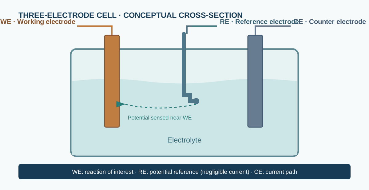
The reference electrode should be positioned close to the working-electrode surface, often through a Luggin capillary when appropriate. This reduces the uncompensated solution resistance between the reference sensing point and the working electrode. It must not obstruct the working-electrode surface or create an unwanted local flow field.
A two-electrode cell is appropriate for many device-level measurements, batteries and symmetric cells, but its measured voltage includes contributions from both electrodes. Do not describe a two-electrode cell voltage as an isolated working-electrode potential versus a reference electrode.
3. How the instrument controls the cell
A potentiostat combines a command signal, a feedback controller, a control amplifier, current measurement electronics and voltage-sensing inputs. The controller continuously adjusts the counter-electrode drive so that the sensed WE–RE potential follows the requested waveform.

Main functional blocks
- Command generator: produces a constant potential, ramp, triangular waveform, pulse sequence or programmed waveform.
- Reference-potential sensing: measures the WE potential relative to the RE with a high-input-impedance voltage channel.
- Error amplifier / controller: compares command and measured potential.
- Control amplifier: drives the counter electrode to reduce the control error.
- Current measurement: measures current through a transimpedance amplifier, shunt or selectable current range.
- Digitizer and software: samples voltage and current, applies range and filtering settings, stores data and displays the result.
The exact circuit topology differs among manufacturers and models. The diagram is a functional representation, not a model-specific schematic.
Feedback is not unlimited
The control amplifier has finite output voltage, output current and bandwidth. If the cell requires more drive than the instrument can supply, the potentiostat reaches its compliance limit and can no longer maintain the requested WE potential. The displayed potential may then depart from the command waveform.
Compliance is therefore a measurement validity condition, not merely a software setting. Inspect raw potential, current and overload/status indicators during demanding experiments.
4. Current ranges, resolution and compliance
Electrochemical currents can span many orders of magnitude. Instruments use selectable current ranges or autoranging to balance resolution, noise and maximum measurable current.
- A range that is too high can reduce effective resolution for a small current.
- A range that is too low can saturate or overload during a current transient.
- Range changes can introduce settling transients or discontinuities.
- Filtering can suppress noise but also distort fast transients.
Record the current range, sampling interval, filter settings, applied waveform and any overload events. For low-current measurements, assess leakage, cable insulation, contamination and shielding.
5. Two-wire, three-electrode and four-terminal connections
The cell wiring must follow the instrument manufacturer’s terminal definitions. Some instruments provide separate sense and current leads for the working electrode, while others combine terminals internally or use dedicated cell cables.
Use the correct cable and connector configuration for the exact instrument model. Do not infer terminal assignments from colour alone.
For low-impedance cells or high-current experiments, lead and contact resistance can produce a significant voltage drop. A four-terminal or Kelvin arrangement can separate current delivery from voltage sensing where supported. The reference lead remains a potential-sensing connection and should not carry appreciable current.
iR drop and uncompensated resistance
The potential at the interface is not necessarily identical to the potential sensed at a remote reference electrode. A simplified relation is:
[ E_{interface} E_{measured} - iR_u ]
where (i) is current and (R_u) is uncompensated resistance between the interface and reference sensing point. The sign depends on the current and potential convention.
Possible strategies include moving the reference tip closer, using an appropriate electrolyte/supporting-electrolyte concentration, measuring resistance independently, or applying carefully validated compensation. Excessive positive-feedback compensation can destabilize the control loop and create oscillations. Always report whether and how iR compensation was applied.
6. Common electrochemical techniques
Cyclic voltammetry (CV)
The potential is swept between two limits and then reversed, often at a constant scan rate. Current is plotted against potential. CV can reveal redox features, capacitive response, kinetic limitations and changes in electrochemical reversibility.
For a triangular waveform, the scan rate is:
[ v = ]
Peak current and peak separation depend on scan rate, diffusion, electron-transfer kinetics, electrode area, concentration, uncompensated resistance and cell geometry. A CV curve alone does not prove a unique reaction mechanism.
Linear sweep voltammetry (LSV)
Potential is swept in one direction while current is recorded. It is commonly used to examine onset behaviour, catalytic polarization and limiting-current regions. Report the scan direction, reference scale, scan rate, rotation or stirring condition, gas environment and electrode loading where relevant.
Chronoamperometry (CA)
A potential step or sequence of potential steps is applied and current is recorded as a function of time. The response may include double-layer charging, faradaic reaction, mass transport and instrumental settling. Do not assign the entire early-time transient to a single electrochemical process without checking the time response and cell configuration.
Chronopotentiometry (CP)
A current step is applied and potential is recorded versus time. Potential changes can reflect interfacial kinetics, concentration polarization, phase changes, ohmic drop and depletion near the electrode.
Galvanostatic cycling
Current is controlled during charge/discharge or repeated electrochemical operation. Voltage limits, current density, active area, cut-off criteria, rest periods and temperature must be reported.
EIS is treated as a separate measurement topic in this library. Although many potentiostats support frequency-response measurements, the principles, wiring checks, perturbation validation and impedance interpretation require a dedicated guide.
7. Practical workflow before collecting data
- Define the electrochemical question. Select the controlled variable, potential window, current range and relevant time scale.
- Inspect the cell. Confirm electrode identity, exposed area, electrolyte compatibility, seals, electrical contacts and absence of unintended short circuits.
- Check the reference electrode. Verify type, filling solution, junction condition, storage history and compatibility with the electrolyte.
- Place the reference correctly. Minimize uncompensated resistance without blocking the working electrode.
- Inspect the instrument limits. Set a suitable current range, compliance limit, potential window and sampling interval.
- Run an appropriate baseline. Use a blank electrolyte or control specimen when scientifically justified.
- Check stability. Allow the cell to reach the required temperature, gas composition and open-circuit stability.
- Collect and inspect raw data. Look for overload flags, sudden discontinuities, drift, oscillation and unexpected sign changes.
- Repeat a representative measurement. Check reproducibility and distinguish specimen behaviour from setup artefacts.
- Document the complete setup. Preserve cell diagram, electrode area, reference scale, electrolyte, temperature, gas, waveform and instrument settings.
8. Verification and troubleshooting
Dummy-cell checks
A resistor-capacitor dummy cell can be used to verify basic instrument response, wiring and software operation without an electrochemical reaction. A simple series or parallel RC network produces a predictable electrical response over a defined frequency and amplitude range. Use a manufacturer-recommended dummy cell or a properly rated, documented test fixture.
Dummy-cell verification does not validate the chemistry, reference electrode, cell geometry or electrochemical interpretation.
Open-circuit and short-circuit checks
Perform only the checks described in the instrument manual and with the correct test fixture. Never short arbitrary terminals or connect/disconnect a live cell outside the manufacturer’s procedure. Confirm that measured zero/current offsets and open-circuit readings are within the instrument’s stated specifications.
Common symptoms
| Symptom | Possible causes | Checks |
|---|---|---|
| Potential does not follow command | Compliance reached, poor contact, incorrect wiring, unstable reference | Status flags, cable map, reference condition, cell resistance |
| Current overload | Wrong range, short circuit, excessive electrode area or transient | Cell continuity, range, compliance and electrode geometry |
| Noisy current | Ground loops, shielding, leakage, unstable contacts, gas bubbles | Cable routing, Faraday cage where suitable, insulation, contact stability |
| Potential oscillation | Excessive iR compensation, capacitive cell, unstable control loop | Disable/reduce compensation, inspect cell capacitance and wiring |
| Drifting baseline | Reference drift, changing surface, temperature or composition | Reference check, OCP stability, environmental control |
| Unexpected sign | Lead polarity, sign convention, reaction direction | Verify WE/CE connections and software convention |
9. Calibration, validation and reporting
Calibration and verification are not the same. Calibration establishes the relationship between instrument indication and a reference standard under defined conditions. Verification checks whether the instrument meets specified performance requirements.
Follow the model-specific procedure for potential accuracy, current accuracy, timing, range transitions and output compliance. Use traceable standards or manufacturer-approved fixtures where required. Keep calibration records and note the date and operating conditions.
A reproducible report should include:
- instrument manufacturer, model and relevant firmware/software version;
- two- or three-electrode configuration and a labelled cell diagram;
- working, reference and counter electrode materials and exposed areas;
- reference-electrode type and potential scale;
- electrolyte composition, concentration, pH where relevant and temperature;
- gas composition, flow and pressure when controlled;
- waveform, potential limits, scan rate or current density, sampling interval and hold times;
- current range, compliance limits, filtering and iR compensation;
- conditioning procedure, replicate count and uncertainty or variability.
10. Safety and limitations
Electrochemical systems can combine corrosive electrolytes, flammable gases, high temperatures, pressure, toxic products and electrically energized equipment. Use appropriate PPE, ventilation, gas detection, pressure relief, compatible tubing and institutional procedures. Fuel-cell and electrolyzer test stations require dedicated gas and exhaust safeguards; a potentiostat alone does not provide those protections.
Never exceed the rated voltage, current, power or compliance limits of the instrument, cables, cell and electrodes. Disconnect the cell before changing wiring unless the manufacturer explicitly permits live switching.
11. Manufacturers and technical documentation
The following manufacturers provide potentiostats, galvanostats or electrochemical measurement systems. Product capabilities, channel count, current range, bandwidth and supported techniques vary by model and configuration.
- Gamry Instruments — potentiostats, galvanostats and electrochemical applications.
- BioLogic — potentiostats/galvanostats and electrochemical workstations.
- Metrohm Autolab — modular electrochemical instrumentation.
- AMETEK Princeton Applied Research — electrochemical measurement systems.
- Ivium Technologies — potentiostats and electrochemical analysers.
Use the official manual for the exact model to confirm terminal assignments, compliance, cell-cable configuration, grounding, calibration and safety procedures.
Key takeaways
- A potentiostat controls WE potential relative to RE and measures current.
- A galvanostat controls current and measures potential.
- The reference electrode senses potential; it should not carry the cell current.
- Compliance limits, uncompensated resistance, reference placement and wiring can determine whether the measurement is valid.
- A clean-looking voltammogram is not proof of correct wiring, calibration or mechanistic interpretation.