Four-Point Probe: Sheet Resistance and Resistivity Measurements
Four-Point Probe
ELECTROCHEMICAL & ELECTRICAL MEASUREMENTS · TOPIC 02.03 · RESISTIVITY
A four-point probe measures voltage between two inner contacts while current is passed through two outer contacts. Separating current injection from voltage sensing reduces the influence of lead and contact resistance in the voltage measurement. It does not remove every geometrical, surface or material-related correction.
1. Why four contacts?
In a two-terminal measurement, the measured voltage can include specimen resistance, lead resistance and contact resistance. In a four-terminal measurement, the voltmeter draws negligible current through the inner voltage contacts, so the voltage drop across their contact resistance is usually small.
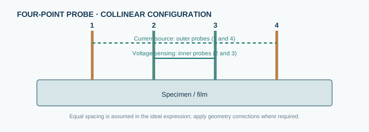
The outer probes supply current (I). The inner probes sense potential difference (V). For a homogeneous, sufficiently thin sheet with equally spaced collinear probes on a large specimen, the ideal sheet-resistance expression is:
[ R_s= ]
This ideal expression assumes a specific geometry and boundary condition. It is not a universal formula for every pellet, thick sample, small coupon or irregular specimen.
2. Sheet resistance versus resistivity
Sheet resistance is expressed in ohms per square ((/)). For a uniform film of thickness (t), bulk resistivity is:
[ =R_s t ]
and conductivity is:
[ = ]
The thickness must be measured independently and should represent the electrically active layer. For porous, cracked, graded or multilayer specimens, a single thickness may not adequately describe the current path.
3. Geometry and correction factors
Finite sample dimensions, probe spacing, specimen thickness, probe placement near edges, anisotropy and nonuniform current distribution modify the ideal result. A more general expression is:
[ R_s=F, ]
where (F) is a geometry/thickness correction factor selected for the actual measurement configuration and the convention used by the instrument or standard.
Do not choose a correction factor by visual approximation. Use the manufacturer’s method, an applicable standard or a validated numerical model. State the factor and its source.
4. Measurement procedure
- Clean the specimen without changing its surface chemistry or damaging a functional layer.
- Measure thickness at representative positions and document spatial variation.
- Inspect probe tips, spacing, spring force and electrical continuity.
- Place the specimen on a stable, electrically appropriate support.
- Position the probe head perpendicular to the surface; avoid excessive force or sliding.
- Select a current low enough to avoid Joule heating, nonlinear conduction or contact damage.
- Measure voltage at multiple current polarities when the instrument supports reversal; this helps identify thermal EMF offsets.
- Repeat at multiple positions and record position dependence.
- Check linearity by measuring several current levels within the non-heating regime.
- Report raw V/I values, geometry correction, thickness and uncertainty.
5. Common errors
| Error source | Consequence | Control |
|---|---|---|
| Poor or unstable contact | Noisy or drifting voltage | Inspect tips, force and surface |
| Sample too small | Boundary-condition error | Apply validated finite-size correction |
| Thickness uncertainty | Direct error in calculated resistivity | Map thickness and report method |
| Joule heating | Current-dependent apparent resistance | Reduce current and test linearity |
| Thermal EMF | Offset in low-voltage measurements | Reverse current and average appropriately |
| Anisotropy or texture | Position/orientation-dependent result | Measure orientations and state assumptions |
| Porosity/cracks | Effective conductivity differs from dense bulk | Document microstructure and current path |
6. Applicability to ceramic pellets and films
A dense, flat pellet may be measured with a four-point probe, but the ideal infinite-sheet formula may be inappropriate when thickness is comparable to probe spacing or lateral dimensions are limited. For bulk ceramics, a four-terminal bar geometry or a guarded fixture may be more suitable, depending on resistivity and sample form.
For thin films, verify continuity, substrate leakage, film thickness and whether the substrate contributes to the measured current. A four-point probe does not automatically isolate a film from a conductive substrate.
7. Verification and reporting
Check the instrument with a suitable resistance standard or verification wafer. Verify current-source accuracy, voltage measurement, probe spacing and correction-factor implementation. Record probe head, spacing, current, voltage, specimen dimensions, thickness, support/substrate, measurement positions, polarity method and uncertainty.
Manufacturers and technical resources: - Jandel Engineering — four-point probe systems and accessories. - Signatone — probe stations and resistivity measurement systems. - Keithley / Tektronix — source-measure and low-level electrical measurement instruments.
The correction factor and measurement limits are instrument- and geometry-dependent. Consult the exact probe-head and meter documentation.