The Reciprocal Lattice: Reciprocal Vectors, Crystal Planes, and X-ray Diffraction
1. Why do we need the reciprocal lattice?
The direct lattice describes the periodic arrangement of points in real space. The reciprocal lattice is a mathematical construction that describes spatial periodicity in terms of wavevectors. It is particularly useful in diffraction because X-rays interact with the periodic electron density of a crystal, and the diffraction condition is naturally expressed using reciprocal-space vectors.
The reciprocal lattice provides a compact way to understand:
- why a reciprocal-lattice vector is normal to a family of crystal planes;
- how Miller indices identify reciprocal-lattice points;
- why the magnitude of a reciprocal vector is related to interplanar spacing;
- how the Laue and Bragg diffraction conditions are expressed;
- how diffraction geometry is represented by the Ewald sphere.
2. The direct lattice and its basis vectors
A three-dimensional direct lattice is generated by three non-coplanar basis vectors (,,). Every lattice translation is
\[ \mathbf{R}=u\mathbf{a}+v\mathbf{b}+w\mathbf{c}, \]
where (u,v,w) are integers.
The unit-cell volume is
\[ V=\mathbf{a}\cdot(\mathbf{b}\times\mathbf{c}). \]
The direct-lattice vectors define the periodicity of the crystal in real space. Their lengths and mutual angles are the familiar unit-cell parameters (a,b,c,,,).
3. Definition of the reciprocal basis
There are two common conventions for reciprocal-lattice vectors. It is essential to state which one is being used.
In the crystallographic convention, which does not include a factor of (2), the reciprocal basis vectors are defined as
\[ \mathbf{a}^{*}=\frac{\mathbf{b}\times\mathbf{c}}{V}, \qquad \mathbf{b}^{*}=\frac{\mathbf{c}\times\mathbf{a}}{V}, \qquad \mathbf{c}^{*}=\frac{\mathbf{a}\times\mathbf{b}}{V}. \]
They satisfy
\[ \mathbf{a}^{*}\cdot\mathbf{a}=1, \quad \mathbf{a}^{*}\cdot\mathbf{b}=0, \quad \mathbf{a}^{*}\cdot\mathbf{c}=0, \]
with equivalent cyclic relations. In compact form,
\[ \mathbf{a}^{*}\cdot\mathbf{a}=1, \qquad \mathbf{a}^{*}\cdot\mathbf{b}=0 \]
and similarly for the other pairs. The reciprocal basis is therefore dual to the direct basis.
Some physics texts instead define reciprocal vectors with a factor of (2), so that (^{*}=2). Both conventions are valid, but equations involving wavevectors and diffraction must be used consistently. This article uses the crystallographic convention without (2), except where the scattering vector is explicitly defined.
4. Reciprocal-lattice vectors
A reciprocal-lattice vector is an integer combination of the reciprocal basis vectors:
\[ \mathbf{G}_{hkl} =h\mathbf{a}^{*}+k\mathbf{b}^{*}+l\mathbf{c}^{*}, \]
where (h,k,l) are integers.
The reciprocal lattice is itself a lattice. Its points are indexed by integer triplets ((hkl)), and each reciprocal vector corresponds to a set of lattice planes in the direct crystal.
With the no-(2) convention, the reciprocal vector has units of inverse length, such as Å(^{-1}).
5. Why is the reciprocal vector normal to the (hkl) planes?
A family of parallel planes with Miller indices ((hkl)) can be represented by the equation
\[ hx+ky+lz=n, \]
where (x,y,z) are fractional coordinates and (n) labels successive planes in the family.
The Cartesian position is
\[ \mathbf{r}=x\mathbf{a}+y\mathbf{b}+z\mathbf{c}. \]
Using the reciprocal basis, the reciprocal vector is
\[ \mathbf{G}_{hkl} =h\mathbf{a}^{*}+k\mathbf{b}^{*}+l\mathbf{c}^{*}. \]
Taking its dot product with the position vector gives
\[ \mathbf{G}_{hkl}\cdot\mathbf{r} =hx+ky+lz=n. \]
A surface of constant dot product with a vector is perpendicular to that vector. Therefore, (_{hkl}) is normal to the (hkl) planes.
This is the geometric reason reciprocal space is so effective for describing diffraction from crystal planes.
6. The relationship between reciprocal-vector magnitude and d-spacing
For two adjacent planes, the value of (n) changes by one. The perpendicular distance between them is therefore
\[ d_{hkl}=\frac{1}{|\mathbf{G}_{hkl}|}. \]
This equation uses the reciprocal-lattice convention without (2). If the reciprocal basis includes (2), the corresponding expression is (|{hkl}|=2/d{hkl}).
For a cubic crystal with lattice parameter (a),
\[ |\mathbf{G}_{hkl}| =\frac{\sqrt{h^2+k^2+l^2}}{a}, \]
and hence
\[ d_{hkl}=\frac{a}{\sqrt{h^2+k^2+l^2}}. \]
Worked example. For a cubic material with (a=4.00) Å, the (110) reciprocal vector has magnitude
\[ |\mathbf{G}_{110}|=\frac{\sqrt{2}}{4.00} =0.3536\ \text{Å}^{-1}, \]
so
\[ d_{110}=\frac{1}{0.3536}=2.828\ \text{Å}. \]
7. Reciprocal-cell parameters
The reciprocal lengths are related to the direct-cell parameters by
\[ a^*=\frac{bc\sin\alpha}{V}, \quad b^*=\frac{ca\sin\beta}{V}, \quad c^*=\frac{ab\sin\gamma}{V}. \]
The reciprocal angles are
\[ \cos\alpha^*=\frac{\cos\beta\cos\gamma-\cos\alpha} {\sin\beta\sin\gamma}, \]
with cyclic expressions for (^) and (^).
For a cubic cell, the reciprocal cell is also cubic and (a*=b=c^=1/a). For lower-symmetry cells, the reciprocal metric is generally different from the direct metric.
A general expression for the interplanar spacing is
\[ \frac{1}{d_{hkl}^{2}} =|\mathbf{G}_{hkl}|^2. \]
Expanding this using the reciprocal-cell parameters gives
\[ \begin{aligned} \frac{1}{d_{hkl}^{2}}={}&h^2a^{*2}+k^2b^{*2}+l^2c^{*2}\\ &+2klb^*c^*\cos\alpha^* +2hla^*c^*\cos\beta^* +2hka^*b^*\cos\gamma^*. \end{aligned} \]
This form is valid for a general unit cell when the reciprocal parameters are defined consistently.
8. Diffraction as a change in wavevector
An incident X-ray wave can be described by a wavevector ({i}), and the diffracted wave by ({f}). For elastic scattering, the magnitudes are equal:
\[ |\mathbf{k}_{i}|=|\mathbf{k}_{f}|=\frac{1}{\lambda}. \]
Here the wavevector convention is crystallographic (no (2)). The scattering vector is
\[ \mathbf{q}=\mathbf{k}_{f}-\mathbf{k}_{i}. \]
For constructive diffraction from a periodic crystal, the scattering vector must match a reciprocal-lattice vector:
\[ \mathbf{q}=\mathbf{G}_{hkl}. \]
If wavevectors are instead defined with a factor of (2), then their magnitudes are (2/), and the same physical condition is written with the correspondingly scaled reciprocal vector.
This vector condition is the Laue diffraction condition. It is equivalent to Bragg’s law for the appropriate family of lattice planes.
9. Deriving Bragg’s law from reciprocal space
The magnitude of the scattering vector for elastic scattering through an angle (2) is
\[ |\mathbf{q}|=2|\mathbf{k}|\sin\theta =\frac{2\sin\theta}{\lambda}. \]
Since (={hkl}) and (|{hkl}|=1/d_{hkl}),
\[ \frac{1}{d_{hkl}}=\frac{2\sin\theta}{\lambda}. \]
Rearranging gives first-order Bragg’s law:
\[ \lambda=2d_{hkl}\sin\theta. \]
The more general form is
\[ n\lambda=2d_{hkl}\sin\theta, \]
where higher diffraction orders can equivalently be represented by integer multiples of the reciprocal vector. In routine crystallographic indexing, reflections are normally labelled by their integer Miller indices, and the order is incorporated into those indices.
10. The Ewald sphere
The Ewald construction is a geometric way to visualize the diffraction condition in reciprocal space.
For the no-(2) convention:
- the incident wavevector has length (1/);
- the diffracted wavevector has the same length for elastic scattering;
- the difference between them is the scattering vector;
- diffraction occurs when a reciprocal-lattice point lies on the Ewald sphere under the chosen origin and vector construction.
In the common construction, the incident wavevector is drawn from the reciprocal-space origin to the sphere centre, and the sphere radius is (1/). A reciprocal-lattice point on the sphere satisfies the elastic diffraction condition.
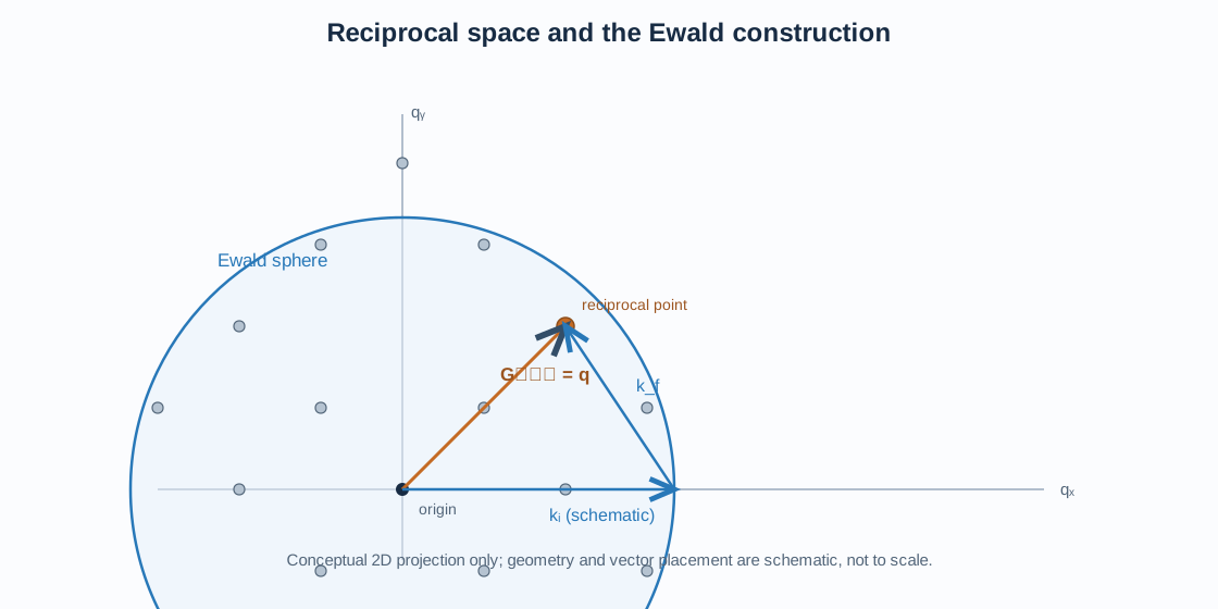
In a single-crystal experiment, rotating the crystal changes the orientation of the reciprocal lattice relative to the Ewald sphere, bringing different reciprocal-lattice points into diffraction condition. In a powder, the crystallites have many orientations, so the diffraction condition can be met for each allowed family of planes over a range of orientations.
11. Reciprocal lattice and powder XRD
In powder diffraction, each observed peak is associated with a set of lattice planes and therefore a reciprocal-lattice vector magnitude. For a fixed wavelength, the peak position is determined by (d_{hkl}) through Bragg’s law.
The reciprocal lattice helps separate three questions:
- Peak position: determined mainly by the unit-cell metric and the magnitude of the reciprocal vector.
- Reflection condition: determined by translational symmetry, centering, screw axes, and glide planes.
- Peak intensity: determined by the structure factor, atomic scattering factors, occupancies, coordinates, and displacement parameters.
A reciprocal-lattice point may be geometrically defined but have zero structure factor because of a systematic absence. Thus, reciprocal-lattice geometry alone does not guarantee an observable reflection.
For practical powder-pattern interpretation, combine the calculated d-spacings with the space-group reflection conditions and the structural model.
12. Direct lattice, reciprocal lattice, and Miller indices: a comparison
| Concept | Direct space | Reciprocal space |
|---|---|---|
| Basis | (,,) | (*,,^) |
| Lattice vector | () | (_{hkl}) |
| Coordinates | Real-space position | Spatial frequency / inverse length |
| Main role | Atomic periodicity | Diffraction geometry |
| Plane relationship | (hkl) planes | Normal vector (_{hkl}) |
Miller indices are shared by the plane family in direct space and the corresponding reciprocal-lattice point. The indices identify the orientation and spacing of the planes through the reciprocal vector.
13. Practical workflow for XRD and crystallographic analysis
- Confirm the unit cell. Record the direct-cell lengths and angles and verify the space-group setting.
- Calculate reciprocal parameters. Use the reciprocal-basis definitions or a crystallographic program.
- Generate candidate reciprocal vectors. Enumerate integer ((hkl)) values within the required resolution range.
- Calculate d-spacings. Use (d_{hkl}=1/|_{hkl}|) under the no-(2) convention.
- Convert to diffraction angles. Apply Bragg’s law using the actual wavelength and radiation configuration.
- Apply reflection conditions. Remove systematically absent reflections for the space group.
- Compare with measured data. Check peak positions first, then assess intensities using a structure-factor or Rietveld model.
In GSAS-II, the phase unit cell and space group define the reciprocal metric and reflection list. In VESTA, reciprocal-space concepts help interpret plane orientations and diffraction-related geometry. Always check the reciprocal-vector convention when comparing numerical values from different programs or textbooks.
14. Common mistakes
- Mixing reciprocal definitions with and without (2).
- Using (||=1/d) with a reciprocal basis that includes (2).
- Assuming the reciprocal and direct unit cells have identical angles in non-cubic systems.
- Treating every reciprocal-lattice point as an allowed diffraction reflection.
- Confusing the scattering angle (2) with the Bragg angle ().
- Forgetting that the Ewald sphere construction depends on the wavelength and crystal orientation.
- Treating reciprocal-lattice vectors as atomic positions; they describe periodicity, not atom coordinates.
15. Key points
The reciprocal lattice is the natural mathematical language of diffraction. Its basis vectors are dual to the direct-lattice basis, and each integer triplet ((hkl)) defines a reciprocal vector normal to the corresponding family of direct-lattice planes. With the crystallographic convention used here, its magnitude is the inverse interplanar spacing. The diffraction condition requires the scattering vector to coincide with a reciprocal-lattice vector, providing a reciprocal-space derivation of Bragg’s law and the Ewald construction.
Further reading
References
- B. D. Cullity and S. R. Stock, Elements of X-Ray Diffraction, 3rd ed., Prentice Hall, 2001.
- International Union of Crystallography, International Tables for Crystallography, Volume A: Space-Group Symmetry.
- C. Kittel, Introduction to Solid State Physics, reciprocal lattice and diffraction chapters.
- B. E. Warren, X-ray Diffraction, Dover Publications, 1990.