Bragg Reflections and Crystal Planes: What Does an XRD Peak Actually Represent?
1. The question behind every XRD peak
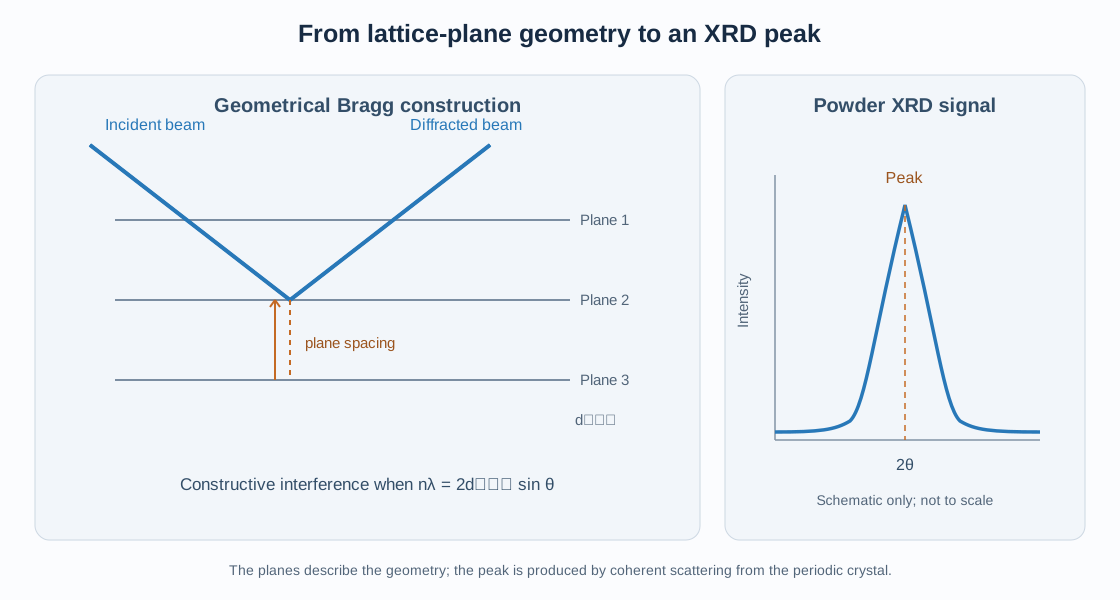
When an X-ray diffraction pattern is measured, the detector records intensity as a function of scattering angle, commonly plotted as intensity versus (2). Each peak is associated with constructive interference from the periodic electron density of a crystalline material.
A common shorthand is to say that a peak comes from a particular set of crystal planes, such as (110) or (200). This is useful, but it can lead to a misleading picture: an XRD peak is not a direct image of a physical sheet of atoms reflecting X-rays like a mirror.
The planes are a geometrical description of the periodic crystal lattice. The diffraction peak arises from coherent scattering by the electrons throughout the crystal, with the contributions from the atoms adding with particular phases.
This article connects the geometrical picture of Bragg planes with the more complete reciprocal-space and structure-factor descriptions.
2. What is a family of lattice planes?
A crystal lattice is periodic in three dimensions. A family of parallel lattice planes can be indexed by Miller indices ((hkl)). These indices describe the orientation and spacing of the plane family relative to the crystallographic axes.
For a conventional unit cell, the intercept method gives the indices from the reciprocals of the plane’s intercepts measured in lattice-parameter units. A plane parallel to an axis has an infinite intercept along that axis and therefore a zero corresponding Miller index.
The notation matters:
- ((hkl)): one particular plane orientation and position in the conventional indexing description;
- ({hkl}): a family of symmetry-equivalent plane orientations;
- ([uvw]): one crystallographic direction;
- (uvw): a family of symmetry-equivalent directions.
The planes in a family are parallel and equally spaced. Their perpendicular separation is the interplanar spacing, (d_{hkl}).
A set of lattice planes is not necessarily a set of occupied atomic layers. The geometrical planes can pass through different parts of the unit cell, and the electron density on a plane need not be uniform.
3. Interplanar spacing and the unit cell
The value of (d_{hkl}) is determined by the unit-cell metric and the Miller indices. For a cubic crystal,
\[ d_{hkl}=\frac{a}{\sqrt{h^2+k^2+l^2}}, \]
where (a) is the cubic lattice parameter.
For an orthorhombic cell,
\[ \frac{1}{d_{hkl}^{2}}= \frac{h^2}{a^2}+\frac{k^2}{b^2}+\frac{l^2}{c^2}. \]
For a general crystal system, the reciprocal metric provides the most compact expression:
\[ \frac{1}{d_{hkl}^{2}}= |h\mathbf{a}^{*}+k\mathbf{b}^{*}+l\mathbf{c}^{*}|^2, \]
when reciprocal basis vectors are defined without the factor (2).
The spacing is a geometrical property of the lattice. It does not by itself tell us whether a reflection will be intense or even allowed by the full crystal symmetry.
4. What does Bragg’s law actually mean?
Consider waves scattered from successive parallel lattice planes. For a scattering geometry in which the incident and diffracted beams make an angle () with the planes, the path difference between contributions associated with adjacent planes is
\[ \Delta=2d_{hkl}\sin\theta. \]
Constructive interference occurs when this path difference is an integer number of wavelengths:
\[ \boxed{n\lambda=2d_{hkl}\sin\theta} \]
where (n) is an integer diffraction order and () is the X-ray wavelength.
Bragg’s law is a geometrical condition for constructive interference. It predicts the scattering angle associated with a plane spacing for a specified wavelength. It does not, on its own, calculate the intensity or determine whether the reflection is systematically absent.
The term Bragg reflection describes the diffracted beam satisfying this condition. It should not be interpreted as ordinary specular reflection from a material surface.
5. Why the plane picture is useful but incomplete
The Bragg construction is an intuitive way to understand the angular positions of diffraction peaks. However, the actual scattering process is the coherent sum of waves scattered by electrons throughout the crystal.
The more complete description uses the scattering vector:
\[ \mathbf{q}=\mathbf{k}_{f}-\mathbf{k}_{i}, \]
where ({i}) and ({f}) are the incident and final wavevectors. With the crystallographic no-(2) convention, their magnitudes are (1/).
The diffraction condition is
\[ \mathbf{q}=\mathbf{G}_{hkl}, \]
where (_{hkl}) is a reciprocal-lattice vector. Its magnitude is
\[ |\mathbf{G}_{hkl}|=\frac{1}{d_{hkl}}. \]
Combining this condition with elastic scattering gives Bragg’s law. The reciprocal-space description is more general and is especially useful for single-crystal diffraction and diffraction geometry.
6. What is an XRD reflection?
In crystallography, a reflection is conventionally labelled by Miller indices ((hkl)). It refers to a reciprocal-lattice vector and the corresponding diffraction condition.
The word reflection is historical crystallographic terminology. It does not mean that a single physical plane acts as a mirror. The measured diffracted intensity results from the coherent scattering of the crystal’s periodic electron density.
A reflection can be:
- allowed and intense;
- allowed but weak;
- systematically absent because symmetry-related contributions cancel;
- too weak to be detected under the experimental conditions.
Thus, a geometrically defined ((hkl)) does not guarantee a measurable peak.
7. The role of the structure factor
The structure factor determines the amplitude resulting from the atoms within the unit cell:
\[ F_{hkl}=\sum_j f_j \exp[2\pi i(hx_j+ky_j+lz_j)]. \]
Here (f_j) is the atomic scattering factor and ((x_j,y_j,z_j)) are fractional atomic coordinates.
In the kinematic approximation, the intrinsic intensity associated with an individual reflection is proportional to
\[ I_{hkl}\propto |F_{hkl}|^2. \]
This equation explains why two reflections with similar d-spacings can have very different intensities. Their structure factors may differ because the atoms contribute with different phase relationships.
If the sum cancels exactly, (F_{hkl}=0), and the reflection is systematically absent in the ideal structure-factor model. Lattice centering, glide planes, and screw axes can impose such reflection conditions.
8. One peak, one reflection, or many reflections?
In a single-crystal diffraction experiment, an individual measured spot is associated with a reciprocal-lattice point satisfying the diffraction condition at that crystal orientation. Depending on symmetry and experimental geometry, several symmetry-related reflections may also be measured.
In a powder experiment, crystallites are distributed over many orientations. For a given d-spacing, crystallites in suitable orientations can satisfy the diffraction condition. The detector therefore records diffraction intensity at the corresponding scattering angle.
A powder peak can contain contributions from multiple symmetry-equivalent reflections with the same d-spacing. Their contributions are grouped in the powder pattern and are accounted for through the reflection multiplicity in the calculated intensity.
Different, non-equivalent reflections can also overlap when their d-spacings are similar or identical. Therefore, one observed powder peak does not always correspond to only one unique ((hkl)) reflection.
9. Why do some expected peaks not appear?
There are several distinct reasons why a reflection may be missing or difficult to observe.
9.1 Systematic absences
The space-group symmetry can force the structure factor to zero for particular index conditions. For example, an I-centred lattice has the centering condition
\[ h+k+l=2n. \]
Reflections with an odd value of (h+k+l) are absent for the I-centering translation when the conventional cell represents the corresponding translational symmetry.
9.2 Very low structure-factor intensity
An allowed reflection may have a small value of (|F_{hkl}|^2) because atomic contributions partially cancel. It may be below the detection limit or hidden by background.
9.3 Experimental and sample effects
Preferred orientation, absorption, microabsorption, finite crystallite size, strain broadening, low phase fraction, peak overlap, and detector sensitivity can affect the measured pattern. These effects should not be confused with symmetry-enforced absences.
9.4 Limited angular range
A reflection may lie outside the measured 2θ range. Its absence from the recorded scan does not imply that it is forbidden.
10. Peak position and peak intensity answer different questions
The position of a peak is primarily connected to the interplanar spacing and wavelength through Bragg’s law. A change in lattice parameters can therefore shift peak positions.
Peak intensity depends on the structure factor and additional experimental and geometrical factors. It is affected by atomic species, coordinates, occupancies, displacement parameters, multiplicity, preferred orientation, absorption, and instrument geometry.
Peak width is a different observable again. It can contain information about coherent domain size, microstrain, defects, and instrumental broadening. A broad peak is not necessarily a weak reflection, and a narrow peak is not necessarily a strong one.
A useful first-pass interpretation is:
| Observable | Main crystallographic information |
|---|---|
| Peak position (2θ) | d-spacing and unit-cell metric |
| Integrated intensity | Structure factor and intensity corrections |
| Peak width/profile | Crystallite size, strain, defects, and instrument response |
| Missing reflection | Possible symmetry extinction, weak intensity, overlap, or measurement limitation |
11. A practical example for a cubic material
For a cubic phase, the first few candidate plane spacings follow
\[ d_{hkl}=\frac{a}{\sqrt{h^2+k^2+l^2}}. \]
The corresponding peak positions are calculated from
\[ 2\theta=2\sin^{-1}\left(\frac{\lambda}{2d_{hkl}}\right) \]
for first-order indexing, provided the argument is physically valid.
However, the candidate list must then be filtered using the space-group reflection conditions and evaluated using the structure factor. For example, a cubic I-centred structure does not allow reflections for which (h+k+l) is odd. A cubic F-centred structure requires (h,k,l) to be all even or all odd for the centering condition.
This illustrates the proper sequence: calculate possible positions from the lattice metric, apply symmetry conditions, and then calculate expected intensities from the structural model.
12. Practical interpretation of a powder XRD pattern
A disciplined workflow separates peak-position analysis from intensity analysis:
- Calibrate the scan. Confirm wavelength, zero shift, sample displacement, and instrument geometry.
- Identify candidate phases. Compare the pattern with plausible phase references and chemical constraints.
- Index peak positions. Determine a consistent unit cell and calculate d-spacings.
- Check reflection conditions. Test whether the candidate space group permits the observed reflections.
- Calculate structure factors. Use atomic coordinates, species, occupancies, and displacement parameters.
- Account for powder multiplicity. Combine contributions from symmetry-equivalent reflections.
- Inspect profile effects. Consider overlap, preferred orientation, size/strain broadening, and background.
- Refine the structural model. Use Rietveld refinement only after the phase, cell, and symmetry model are physically plausible.
In GSAS-II, the phase model and space group determine the reflection list and structure-factor calculations. The calculated pattern is then combined with profile and instrument models. VESTA can help visualize the crystal structure and plane orientations, but a visualization of planes should not be mistaken for a direct representation of the measured diffraction intensity.
13. Common misconceptions
- “An XRD peak is a reflection from one physical atomic sheet.” The planes are a geometrical model; the scattering is coherent and arises from the crystal’s electron density.
- “Every (hkl) plane produces a peak.” Some reflections are systematically absent or too weak to detect.
- “Peak position tells us the atomic arrangement.” Peak positions mainly constrain the lattice metric; intensities provide much of the information about the basis and atomic arrangement.
- “One powder peak always means one reflection.” Multiple equivalent or overlapping reflections can contribute.
- “A missing peak proves a space group.” Absence data must be interpreted with detection limits, overlap, and the full set of reflection conditions.
- “Bragg reflection is ordinary mirror reflection.” It is constructive interference from periodic scattering.
14. Key points
An XRD peak is the measured signature of coherent scattering under a diffraction condition. Miller-indexed planes provide a useful geometrical description of the interplanar spacing, while reciprocal-lattice vectors express the diffraction condition mathematically. The structure factor determines whether the atomic contributions reinforce, partially cancel, or cancel exactly. In powder diffraction, symmetry-equivalent and overlapping reflections can contribute to a single observed peak. Reliable interpretation therefore requires the lattice metric, space-group symmetry, structure factor, and experimental profile to be considered together.
Further reading
- The Crystal Structure Factor: Atomic Scattering, Diffraction Intensities, and Systematic Absences
- The Reciprocal Lattice: Reciprocal Vectors, Crystal Planes, and X-ray Diffraction
- Miller Indices (hkl): Understanding Crystal Planes and Directions
- Understanding Crystallographic Space Groups
- Reading and Interpreting XRD Patterns
- Rietveld Refinement with GSAS-II
References
- B. D. Cullity and S. R. Stock, Elements of X-Ray Diffraction, 3rd ed., Prentice Hall, 2001.
- B. E. Warren, X-ray Diffraction, Dover Publications, 1990.
- H. P. Klug and L. E. Alexander, X-ray Diffraction Procedures, 2nd ed., Wiley, 1974.
- International Union of Crystallography, International Tables for Crystallography, Volume A: Space-Group Symmetry.