Uniaxial Die Pressing and Ceramic Powder Compaction
Uniaxial Die Pressing and Ceramic Powder Compaction
Uniaxial die pressing consolidates a powder charge inside a rigid die by applying force through one or two punches. It is widely used for repeatable, high-throughput production of relatively simple ceramic shapes. Its apparent simplicity hides a coupled problem involving powder flow, granule deformation, interparticle friction, stress transmission, elastic recovery and tooling interactions.
The objective is not simply to reach a high average green density. A useful compact must also have sufficiently uniform density, adequate green strength, acceptable dimensions and no critical defects that will propagate during handling, debinding or sintering.
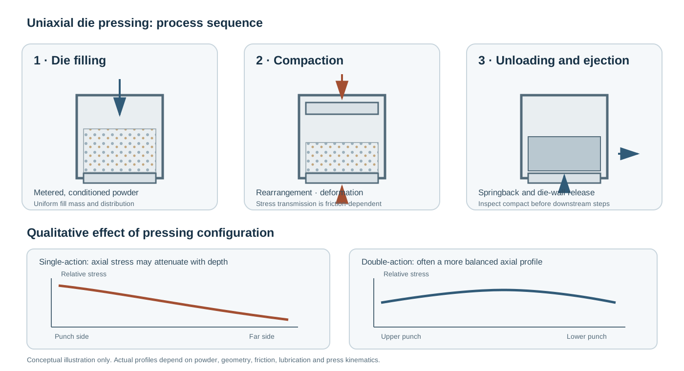
1. Process principle and press configurations
A measured powder charge is introduced into a rigid die cavity. A punch or a pair of punches then reduces the available volume, forcing particles and granules into closer contact. After the load is removed, the compact is ejected.
Three configurations are commonly distinguished:
- Single-action pressing: one punch moves while the opposite die boundary is effectively stationary. Axial stress is progressively attenuated by friction at the die wall.
- Double-action pressing: upper and lower punches move toward one another. This can reduce, but does not automatically eliminate, the axial density gradient.
- Floating-die pressing: the die is allowed to move in response to the transmitted force. The arrangement changes the relative motion and stress distribution and must be treated as a distinct tooling configuration.
The configuration should be reported explicitly. A statement such as “uniaxially pressed” is insufficient to reproduce the stress path.
2. Powder conditioning before pressing
Pressing performance is largely determined before the powder reaches the die. The feed should be sufficiently free-flowing to fill the cavity reproducibly, while retaining a granule structure that can compact without leaving persistent large pores.
2.1 Particle and granule attributes
Important descriptors include:
- Primary-particle size distribution and morphology.
- Agglomerate and granule size distribution.
- Granule strength, deformability and internal porosity.
- Moisture content and sensitivity to ambient humidity.
- Binder and lubricant content and distribution.
- Bulk density, tapped density and flowability.
A broad or unstable granule distribution can cause segregation during transport and die filling. Very strong granules may resist deformation and survive pressing as intergranular defects; very weak granules may break prematurely, changing flow and filling behaviour.
2.2 Granulation and flow
Spray drying is one route to produce pressable granules, but granulation route and operating conditions must be selected for the actual powder chemistry and intended component. Granule size alone is not a sufficient quality metric: shape, strength, internal pore structure and moisture also influence die filling and compaction.
Useful feed-characterization methods include sieve analysis or laser diffraction, flow testing, bulk/tapped-density measurements, moisture analysis and microscopy of granules.
2.3 Binder and lubricant functions
A binder can improve green strength by promoting cohesion between particles or granules. A lubricant can reduce friction at the die wall and/or between particles, depending on its chemistry and addition route. These functions are not interchangeable.
Excessive organic content can increase burnout demand, leave residues or create gas-evolution defects if the debinding schedule is unsuitable. Lubricant distribution is also important: nonuniform addition can produce local differences in compaction and ejection behaviour.
3. Die filling and mass control
The mass delivered to the die controls the nominal compact mass and, together with the final cavity volume, its average green density. Inconsistent filling produces mass variation and can also generate spatial density variation.
A controlled filling sequence should consider:
- Feed-powder conditioning and hopper stability.
- Fill-shoe speed and trajectory.
- Cavity geometry and fill depth.
- Segregation during flow.
- Powder-level consistency and environmental humidity.
- Charge mass and its repeatability.
For development work, record the mass of individual compacts rather than relying only on a nominal machine setting. Monitor both the mean and the spread of fill mass.
4. Mechanics of powder compaction
Compaction is not a single deformation mechanism. Depending on powder and granule properties, it can involve:
- Particle/granule rearrangement: particles move into more efficient packing configurations and large voids are reduced.
- Granule deformation and fragmentation: agglomerates deform, collapse or fracture as contact forces rise.
- Particle deformation and local contact growth: at higher stresses, local elastic or inelastic deformation can increase contact area and green strength.
The relative contribution of each mechanism depends on powder morphology, granule architecture, binder, moisture, friction and applied pressure. These stages overlap; they should not be interpreted as sharply separated universal pressure intervals.
4.1 Nominal compaction pressure
For a punch applying force (F) over projected area (A), the nominal applied pressure is:
[ P_{}= ]
Use consistent units. For example, force in newtons and area in square metres gives pressure in pascals. The nominal pressure is not necessarily equal to the local stress throughout the powder bed because wall friction and internal stress redistribution create spatial variations.
4.2 Pressure–density response
A compaction curve is obtained by measuring compact density as a function of applied pressure. It is useful for comparing feed conditions and identifying changes in packing and deformation behaviour, provided sample geometry, filling protocol and density measurement are consistent.
The Heckel relationship is sometimes used to analyse compaction data:
[ ()=KP+A ]
where (D) is the relative density, (P) is the applied pressure, and (K) and (A) are fitted parameters under the selected model convention. The reciprocal of (K) is often interpreted as an apparent pressure scale associated with deformation. However, the model is not a universal constitutive law: fitting range, initial packing, granule collapse and the assumed deformation mechanism affect interpretation. Do not compare fitted parameters without checking that the same density definition and fitting procedure were used.
5. Green density and its calculation
The bulk green density is:
[ _{}= ]
where (m) is the dry mass represented by the compact and (V_{}) is its measured external volume. For a regular cylindrical compact:
[ V_{}=()^2h ]
where (d) and (h) are the measured diameter and height after the specified unloading/conditioning period.
Relative green density is:
[ D_{}= ]
The theoretical density must correspond to the actual phase assemblage and composition being evaluated. If the compact contains multiple phases, the density basis should be calculated or justified accordingly. Clearly state whether binder, lubricant, moisture or other volatile components are included in the mass.
A single bulk-density value cannot reveal local density gradients. For process development, use suitable spatially resolved methods, section-based measurements, dimensional response, or validated modelling where necessary.
6. Die-wall friction and stress transmission
During pressing, the powder experiences normal pressure against the die wall. Friction at this interface opposes relative movement and reduces the axial stress transmitted through the compact. The effect becomes more consequential as the compact becomes taller relative to its cross-section.
The resulting stress field can produce:
- Axial density gradients, particularly in single-action pressing.
- Radial variations associated with wall constraints and geometry.
- Nonuniform elastic recovery after unloading.
- Local residual stresses that influence ejection and subsequent processing.
Double-action pressing, appropriate tooling, controlled lubrication and improved powder uniformity can reduce some gradients. None should be assumed to guarantee a homogeneous compact.
7. Elastic recovery and springback
After the punch load is released, the compact expands because stored elastic strain is recovered. This is commonly called springback. Recovery can occur axially and radially and may continue after ejection.
Springback depends on the powder’s elastic response, compact density, binder and lubricant system, stress history, die constraint and unloading procedure. Nonuniform recovery can create residual stresses or dimensional changes that contribute to cracking.
Measure dimensions at a defined time after ejection. If immediate and delayed dimensions differ, report the measurement interval and environmental conditions.
8. Ejection and tooling interactions
Ejection is a mechanically demanding stage. The compact must overcome residual radial pressure and friction against the die wall. High ejection force or abrupt motion can initiate cracks even when the compact appeared intact under the punch.
Record, where possible:
- Peak and/or full ejection-force profile.
- Punch and die surface condition.
- Lubrication strategy.
- Ejection speed and stroke.
- Compact damage immediately after ejection.
- Dimensional recovery after ejection.
A smooth force trace is not proof of a defect-free compact, but abnormal peaks, stick-slip behaviour or cycle-to-cycle drift can indicate tooling or feed problems.
9. Typical defects and their mechanisms
| Defect | Typical mechanism | Diagnostic direction |
|---|---|---|
| Capping / end capping | Separation near a compact end, often associated with stress gradients, trapped air, weak intergranular bonding or elastic recovery | Inspect fracture plane; review filling, granule condition, dwell and unloading |
| Lamination | Planar separation approximately parallel to punch faces, potentially linked to trapped air, granule layering or stress release | Examine cross-sections; review filling, deaeration, pressing rate and pressure-release sequence |
| Vertical cracking | Tensile stress during ejection or nonuniform radial recovery | Review die friction, lubrication, ejection force and compact geometry |
| Density bands | Nonuniform filling, segregation, granule response or stress transmission | Map density or microstructure through the compact |
| Edge chipping | Low green strength, handling damage or excessive ejection stress | Check binder distribution, green strength and handling |
| Dimensional variation | Fill-mass variation, die wear, springback or inconsistent press displacement | Track mass, dimensions, tooling condition and press calibration |
| Sintering cracks / warpage | Green-density gradients create differential shrinkage during firing | Compare green-state density distribution with post-sintering distortion |
These are diagnostic associations, not one-to-one rules. A visible defect can have more than one contributing cause; confirm the mechanism using fracture surfaces, cross-sections, force data and controlled trials.
10. Process variables and practical optimization
A useful development plan changes a limited number of variables at a time and tracks both average response and variability.
| Variable | Main response to monitor | Practical caution |
|---|---|---|
| Feed granule distribution | Die filling and packing | Avoid segregation during handling |
| Moisture / binder state | Granule strength and green cohesion | Control conditioning and storage |
| Fill mass and fill sequence | Mass and density uniformity | Do not infer uniformity from mass alone |
| Compaction pressure | Green density, strength and recovery | Higher pressure is not automatically better |
| Pressing rate and dwell | Air escape and time-dependent response | Determine suitable values experimentally |
| Unloading profile | Residual stress and cracking | Avoid assuming instantaneous release is harmless |
| Lubrication | Die friction and ejection | Check contamination and burnout compatibility |
| Die geometry and surface | Stress distribution and ejection | Tooling changes can alter the process window |
A rational optimization sequence is:
- Stabilize powder conditioning and die filling.
- Establish a reproducible mass and dimensional baseline.
- Generate pressure–density and green-strength curves.
- Measure ejection behaviour and springback.
- Assess density uniformity and defect frequency.
- Validate the selected conditions through debinding and sintering.
The target is a robust process window, not the highest pressure or density obtained in a single trial.
11. Characterization and quality control
A practical quality-control package may include:
- Feed: particle/granule size distribution, moisture, flowability and granule morphology.
- Green compact: mass, dimensions, bulk density, relative density and green strength.
- Press cycle: applied force/pressure, displacement, dwell and ejection-force data.
- Defect assessment: visual inspection, sectioning and microscopy where appropriate.
- Downstream validation: dimensional change, shrinkage, warpage, density and microstructure after firing.
For critical components, establish sampling frequency and acceptance criteria from the product requirements and process capability rather than adopting generic thresholds.
12. Single-action versus double-action pressing
| Feature | Single-action | Double-action |
|---|---|---|
| Punch motion | One punch applies the compaction stroke | Opposing punches move toward one another |
| Stress transmission | More strongly affected by distance from the moving punch | Can improve axial stress balance |
| Density distribution | Often more pronounced axial gradient for tall compacts | May reduce axial gradients |
| Tooling/control | Simpler press arrangement | More complex motion coordination |
| Limitation | Wall friction remains important | Does not eliminate radial or local heterogeneity |
The appropriate configuration depends on component geometry, powder response, production rate and tooling constraints.
13. Distinction from cold isostatic pressing
Uniaxial die pressing transmits force through punches in a rigid die. Cold isostatic pressing (CIP) applies fluid pressure around a flexible mould, producing a different stress boundary condition. CIP can be advantageous where more uniform pressure transmission or larger/complex shapes are needed, but tooling, dimensional control, cycle time and mould design differ.
CIP is therefore treated as a separate processing method and should not be described as simply another punch arrangement.
14. Safety and operational controls
Follow the powder’s safety data sheet and local laboratory procedures. Fine ceramic powders may present inhalation hazards; organic binders and lubricants may introduce additional exposure and fire risks. Use suitable containment, local exhaust ventilation, housekeeping and personal protective equipment. Keep hands clear of moving punches and dies, use approved guarding and interlocks, and never reach into a press during an energized cycle.
15. Minimum reporting checklist
For a reproducible uniaxial pressing study, report:
- Powder identity, phase/composition, particle and granule characteristics.
- Granulation route, binder/lubricant identity and content, moisture state.
- Die geometry, material, surface condition and lubrication approach.
- Single-action, double-action or floating-die configuration.
- Fill mass, filling procedure and compact dimensions.
- Applied force or nominal pressure, pressing rate, dwell and unloading profile.
- Ejection procedure and, if available, ejection-force data.
- Density definition, theoretical-density basis and measurement timing.
- Green strength, defect observations and spatial-uniformity assessment.
- Subsequent debinding/sintering conditions when final properties are discussed.
References
- D. E. Niesz, “A Review of Ceramic Powder Compaction,” KONA Powder and Particle Journal 14 (1996), 44–51. https://doi.org/10.14356/kona.1996009
- S. J. Glass and K. G. Ewsuk, “Ceramic Powder Compaction,” MRS Bulletin (1997). https://doi.org/10.1557/S0883769400034709
- K. Yanai and M. Hirai, “Radial Die Wall Pressure during Ceramic Powder Compression and Unloading,” Journal of the Japan Society of Powder and Powder Metallurgy 47 (2000), 353–363. https://doi.org/10.2497/jjspm.47.353
- K. Uematsu, “Processing defects in ceramic powders and powder compacts,” Advanced Powder Technology 25 (2014), 154–162. https://doi.org/10.1016/j.apt.2014.01.009
- J.-C. Boyer et al., “Cumulative Effect of Pressing and Drying on Stress Generation within a Green Ceramic Compact,” Journal of Powder Technology (2014). https://doi.org/10.1155/2014/674782
- C. C. Melo et al., “A validation procedure for numerical models of ceramic powder pressing,” Journal of the European Ceramic Society 38 (2018), 2928–2936. https://doi.org/10.1016/j.jeurceramsoc.2018.01.009
- P. Reynaud et al., “Acoustic emission monitoring of uniaxial pressing of ceramic powders,” Ceramics International 18 (1992), 391–397. https://doi.org/10.1016/0272-8842(92)90071-K