Ceramic Slip Casting: Suspension Preparation, Mold Design and Casting Kinetics
Ceramic Slip Casting: Suspension Preparation, Mold Design and Casting Kinetics
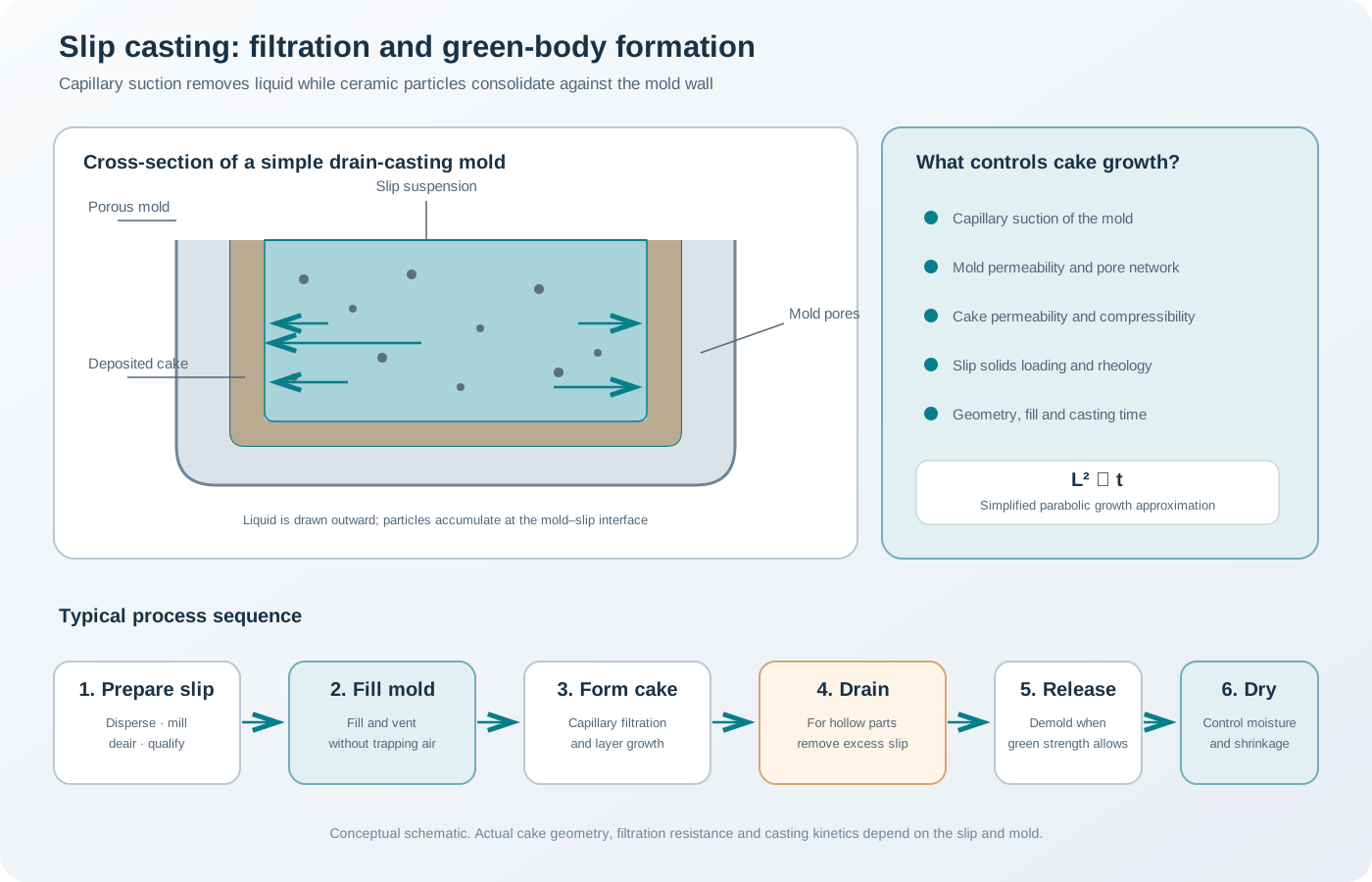
Slip casting is a ceramic forming process in which a concentrated suspension of ceramic particles (the slip) is introduced into a porous mold. The mold draws liquid from the suspension by capillary suction. Particles are retained at the mold surface and build a consolidated layer known as the cast or cake. After the required thickness has formed, excess slip can be drained to produce a hollow article, or the mold can be filled and allowed to form a solid casting.
The process is particularly useful for complex geometries, hollow shapes, undercuts that can be released through multipart molds, and components that are difficult to form by uniaxial pressing. Its success depends on the coupled behaviour of the suspension, porous mold and growing particle cake.
1. Principle: filtration driven by capillary suction
A porous mold creates a pressure difference between the suspension and the liquid entering the mold. The liquid phase migrates through the growing particle layer and into the mold, while most of the ceramic particles are retained at the interface. The deposited particles form a porous cake whose thickness increases with time.
The process contains three coupled transport regions:
- Suspension: particles are transported toward the mold surface as liquid is removed.
- Growing cake: liquid must pass through the deposited particle network, which increasingly resists flow.
- Mold: liquid enters and travels through the interconnected pore network of the mold.
The driving force is primarily capillary suction in conventional plaster-mold casting. The resistance is distributed between the mold and the cake. As the cake thickens, its hydraulic resistance increases, so the casting rate normally decreases with time.
1.1 Drain casting and solid casting
Drain casting - The mold is filled with slip. - A layer forms on the mold wall. - Once the target wall thickness is reached, the remaining liquid slip is drained. - The hollow body remains in the mold until it gains sufficient strength for release.
Solid casting - The mold remains filled while filtration and particle deposition continue. - The body develops inward from the mold surfaces. - The casting is released after sufficient consolidation.
The choice depends on geometry, wall thickness, mold design, production rate and the need to avoid trapped liquid or non-uniform deposition.
2. Suspension design: what makes a good slip?
A ceramic slip is not simply powder mixed with water. It is a concentrated colloidal or particulate suspension that must remain sufficiently stable while flowing and then consolidate reproducibly under the mold’s suction.
The formulation typically contains: - ceramic powder; - liquid medium; - dispersant or deflocculant; - pH-adjusting agent or electrolyte, when required; - optional binder or processing aid, depending on the powder and green-body requirements; - optional antifoaming or wetting additive, where justified.
A suitable slip should combine high enough solids loading for efficient casting and low enough viscosity for filling and mold contact. It should resist hard sedimentation, entrained air and compositional gradients during the casting period.
2.1 Powder characteristics
The following powder properties affect slip behaviour and cast-body packing:
- particle-size distribution and coarse agglomerate fraction;
- particle shape and aspect ratio;
- specific surface area;
- surface charge and surface chemistry;
- moisture and adsorbed species;
- true density;
- tendency to dissolve, hydrolyse or react with the liquid medium.
Fine powders can provide a more uniform microstructure but often have higher surface area and greater dispersant demand. Very fine particles can also reduce cake permeability, slowing liquid transport. A powder that gives excellent suspension stability may therefore cast slowly if the deposited cake is too fine or too densely packed.
2.2 Solids loading
Solids loading is commonly reported as a mass fraction:
[ w_s=% ]
where (m_s) is the mass of ceramic powder and (m_l) is the liquid mass. If dissolved additives are significant, report whether they are included in the denominator.
The solids volume fraction is:
[ _s= ]
where (_s) and (_l) are the true densities of the ceramic solid and liquid, respectively. This conversion is useful because particle crowding and suspension rheology are more directly related to volume fraction than to mass fraction.
Increasing solids loading can: - reduce the volume of liquid that must be removed to form a given body; - reduce drying shrinkage associated with liquid removal; - increase green packing density under suitable dispersion conditions; - increase viscosity and make filling or mold penetration more difficult; - alter the cake structure and permeability.
The optimum is not necessarily the maximum achievable solids loading. It is the composition that gives reproducible filling, adequate filtration rate, uniform packing and a crack-free green body.
2.3 Dispersants and deflocculation
Dispersants reduce attractive particle interactions and help produce a more uniform suspension. Depending on the powder and medium, stabilization may be electrostatic, steric or electrosteric.
In aqueous systems, pH can change surface charge and therefore the magnitude and sign of electrostatic interactions. An electrolyte may compress the electrical double layer and destabilize a suspension, while an appropriate dispersant can provide repulsion or steric stabilization.
The dispersant dose should be determined experimentally. Too little can leave agglomerates and high viscosity. Excess dispersant can increase dissolved organic content, alter ionic strength, produce foaming or interfere with subsequent processing.
Useful screening methods include: - viscosity versus dispersant concentration; - zeta potential as a function of pH, where technically appropriate; - sedimentation and redispersibility; - particle-size distribution after dispersion; - casting rate and green-body uniformity.
A low-viscosity slip is not automatically a good casting slip. Its sedimentation stability, cake packing and release behaviour must also be checked.
2.4 pH and electrolyte control
For aqueous suspensions, pH affects surface hydroxylation, ionization and dispersant adsorption. The pH window is powder-specific. A pH that stabilizes one oxide suspension may destabilize another or promote dissolution of a susceptible powder.
Record the pH after all major additions and after the slip has equilibrated. Also record conductivity when electrolyte concentration is a relevant variable. Do not report a pH value without describing the measurement temperature and calibration practice if precise comparison is required.
2.5 Rheology and thixotropy
The slip must flow during mixing, transfer and mold filling, but excessive low-shear fluidity may permit sedimentation. Some systems exhibit shear thinning or thixotropic recovery.
A power-law approximation is:
[ =K^{n} ]
[ _{app}=K^{n-1} ]
where () is shear stress, () is shear rate, (K) is the consistency index, (n) is the flow index and (_{app}) is apparent viscosity. For (n<1), the fitted region is shear thinning.
A thixotropic suspension loses structure under shear and rebuilds it with time after shear is reduced. This can influence filling, levelling, sedimentation and the initial contact between slip and mold. A flow curve alone does not fully characterize thixotropy; time-dependent recovery tests can be useful.
Report viscosity with the shear rate, geometry, temperature and sample history. A single viscosity number is inadequate for comparing concentrated suspensions.
3. Preparing and conditioning the slip
A general preparation workflow is:
- Powder inspection: verify identity, batch, moisture, particle-size distribution and storage history.
- Liquid preparation: prepare the liquid medium and dissolve or disperse compatible additives.
- pH adjustment: establish a preliminary pH window if the system is aqueous and pH-sensitive.
- Powder addition: add powder gradually under controlled mixing to avoid dry agglomerates.
- Deagglomeration: use suitable high-shear mixing or milling while controlling contamination and temperature.
- Rheology adjustment: optimize dispersant, pH and solids loading based on measured flow behaviour.
- Homogenization: ensure uniform composition throughout the batch.
- Deaeration: remove bubbles that can create voids in the casting.
- Conditioning: allow the slip to reach a reproducible temperature and structural state before use.
- Qualification: measure density, pH, viscosity or flow curve, stability and, where needed, particle-size distribution.
The order of addition is formulation-dependent. A polymeric additive introduced before powder deagglomeration can raise viscosity and hinder dispersion. In another system, a dispersant may need to be adsorbed on the powder before later additions. Establish the sequence through controlled trials.
3.1 Deagglomeration and contamination
Milling can break soft agglomerates and improve uniformity, but milling media and vessel materials may introduce contaminants. Excessive milling can also change particle size, surface area and surface chemistry. Compare the powder before and after processing rather than assuming that longer milling is always beneficial.
3.2 Deaeration
Entrained air can remain trapped at the mold interface or within the growing cast. It can cause pinholes, rounded voids, incomplete filling and local weakness. Vacuum deaeration is commonly used, but the pressure reduction should be controlled to avoid foaming or excessive evaporation. The slip should be checked for bubble release and allowed to recover to a reproducible state before casting.
4. Porous mold design and properties
The mold is an active part of the filtration process. It must provide adequate capillary suction, permeability, mechanical strength, dimensional stability and reliable release.
Plaster-based molds are widely used in conventional slip casting because they are porous, relatively easy to shape and can absorb liquid from the slip. Other porous materials can be used where their pore structure, strength, chemical compatibility and release characteristics are appropriate.
4.1 Mold porosity, pore size and permeability
Three properties must be distinguished:
- Porosity: fraction of mold volume occupied by pores.
- Pore-size distribution: sizes of the connected and non-connected pores.
- Permeability: ability of the connected pore network to transmit liquid.
A high total porosity does not necessarily imply high permeability. Pore connectivity, tortuosity and constrictions matter. Very small pores can generate high capillary suction but may offer high hydraulic resistance. Larger pores can improve permeability but reduce capillary suction. Mold design therefore involves a trade-off rather than simply maximizing porosity.
4.2 Capillary suction
For an ideal cylindrical pore, the capillary pressure can be approximated by:
[ P_{cap}= ]
where () is the liquid surface tension, () is the contact angle and (r) is the effective pore radius.
This idealized expression illustrates why smaller wetting pores can generate greater suction. Real plaster molds have complex pore networks and a distribution of pore sizes, so a single effective radius is only an approximation.
4.3 Mold preparation and conditioning
For plaster molds, preparation variables include: - plaster-to-water ratio; - mixing energy and sequence; - working time before setting; - entrained air; - setting and curing conditions; - drying history; - mold age and repeated-use history.
Increasing the water content in the plaster mix can change the resulting pore structure and mechanical strength. The effect on casting rate is not universally monotonic because capillary suction and permeability change together. A mold that absorbs quickly but is mechanically weak or dimensionally unstable may be unsuitable for production.
Before casting: - inspect the mold for cracks, chips and blocked surfaces; - ensure the mold is sufficiently dry and equilibrated; - check that multipart sections fit and seal correctly; - remove loose particles and contamination; - record the mold’s use history and conditioning procedure.
A wet mold has reduced capacity to absorb additional liquid and can produce slower or less consistent casting. However, aggressive drying can damage a mold or alter its dimensions. Use a controlled conditioning procedure appropriate to the mold material.
5. Casting kinetics: why thickness increases approximately with the square root of time
As the cast layer grows, liquid must travel through an increasingly thick porous cake. The hydraulic resistance therefore increases with thickness. Under simplified conditions, the deposited layer often follows a parabolic growth relationship:
[ L^2=K_c t ]
or
[ L= ]
where (L) is cast-layer thickness, (t) is casting time and (K_c) is an effective casting constant for the defined slip–mold system and process conditions.
This relationship is a useful empirical approximation, not a universal law. It assumes that important properties remain sufficiently constant and that the cake behaves in a suitably simplified manner. Compressible cakes, changing rheology, sedimentation, mold saturation, non-uniform geometry and changing filtration resistance can cause deviations.
5.1 A useful consequence
If the square-root relationship is valid over the tested range, doubling the target thickness requires approximately four times the casting time:
[ =()^2 ]
For example, increasing the target thickness by a factor of 1.5 would require approximately 2.25 times the casting time under the same idealized conditions. This is a scaling estimate, not a process recipe; the actual relationship should be calibrated for the specific mold and slip.
5.2 Darcy’s law and filtration resistance
Liquid transport through a porous medium can be described in simplified form by Darcy’s law:
[ q= ]
where (q) is superficial liquid flow rate per unit area, (K) is permeability, () is liquid viscosity, (P) is pressure drop and () is the flow-path length.
During slip casting, the relevant flow path includes the growing cake and the mold. The total resistance is therefore not constant. As cake thickness increases, its resistance commonly becomes a dominant contribution. This is the physical basis for the declining casting rate.
The more detailed filtration models developed for slip casting account for cake and mold resistance, particle volume fractions and, in some cases, cake compressibility. Their assumptions must be checked before applying them to a particular suspension.
6. Mold filling and casting operation
A controlled casting operation should minimize trapped air, maintain a consistent slip condition and avoid disturbing the growing layer.
A typical sequence is:
- Assemble and seal the mold.
- Verify that the mold is clean, dry and at a controlled condition.
- Homogenize the slip gently without introducing air.
- Fill the mold through a suitable opening at a controlled rate.
- Allow the cast layer to develop for a defined time.
- For drain casting, remove excess slip without damaging the deposited layer.
- Maintain the casting in the mold until it has adequate release strength.
- Open the mold and release the green body carefully.
For complex molds, the location and size of filling and venting openings matter. Air pockets can prevent complete mold contact and create unfilled regions. The mold design should provide a route for displaced air to escape.
6.1 Casting time and wall thickness
Casting time is often used to control wall thickness, but it should be calibrated rather than selected by visual judgement alone. Prepare a calibration curve using the actual slip, mold condition and process temperature.
Measure thickness at multiple positions because local mold permeability, geometry and liquid flow can produce non-uniform deposition. For hollow articles, compare wall thickness near the base, sidewall, rim and geometric transitions.
6.2 Mold orientation and hydrostatic effects
The hydrostatic head of the slip can affect pressure distribution, particularly in tall molds or geometries with substantial vertical extent. Mold orientation and fill level can therefore influence local casting behaviour. In precision work, maintain consistent orientation, fill height and casting conditions.
7. Drain casting: forming hollow bodies
In drain casting, the mold is filled and the cast layer is allowed to reach the required thickness. The remaining slip is then poured out through a drain opening.
The timing of drainage is critical: - draining too early produces thin or weak walls; - draining too late produces excessive thickness and longer cycle time; - slow or incomplete drainage can leave pools of slip and create local thickness variations; - disturbing the mold during drainage can damage the still-weak cast layer.
After drainage, the body remains in the mold while additional liquid is absorbed and the cast gains strength. The release time is distinct from the initial casting time and should be optimized separately.
8. Demolding and green-body handling
A cast body must be strong enough to retain its geometry but not so strongly attached that release causes cracking or surface damage.
Release depends on: - mold moisture and surface condition; - green-body strength; - geometry and undercuts; - wall thickness; - local shrinkage and friction; - multipart mold design and opening sequence.
For complex geometries, multipart molds can reduce mechanical locking. The opening sequence should release the least constrained sections first while supporting fragile regions.
Do not force a body from a mold that has not released. Excessive mechanical force can cause cracks that may not be visible until drying or firing.
9. Drying and shrinkage
After demolding, the green body still contains liquid. Drying causes particle rearrangement, capillary stress and shrinkage. If moisture gradients develop, different regions shrink at different rates and internal stresses can cause cracking or warping.
Important variables include: - wall-thickness distribution; - local packing density; - drying temperature and humidity; - air velocity and direction; - support geometry; - body permeability; - binder or processing-aid content; - geometry and curvature.
Thick sections dry more slowly than thin sections. Abrupt thickness transitions can therefore generate differential shrinkage. A uniform drying environment and suitable support can reduce distortion, but the optimum schedule depends on geometry and material.
9.1 Linear drying shrinkage
A dimensional shrinkage value can be calculated as:
[ S_d=% ]
where (L_{wet}) is the defined dimension at the wet or as-cast stage and (L_{dry}) is the dimension after drying. State precisely when the first measurement is made; the body may already have undergone some consolidation and shrinkage while still in the mold.
9.2 Total process shrinkage
Drying shrinkage and firing shrinkage should be reported separately when possible. If the process has multiple dimensional-change stages, measure each stage rather than reporting only a single final shrinkage value. This helps identify whether distortion originates during casting, drying, debinding or sintering.
10. Defects, causes and diagnosis
| Defect | Possible cause | Diagnostic approach |
|---|---|---|
| Slow casting rate | Low mold permeability, wet mold, high slip viscosity, low capillary suction or low cake permeability | Check mold conditioning, flow curve and cast-thickness versus time |
| Non-uniform wall thickness | Mold permeability variation, poor filling, uneven geometry or inconsistent drain time | Map thickness at defined positions and inspect mold |
| Soft or weak cast | Low solids loading, poor particle packing, inadequate consolidation or unstable slip | Measure solids loading, green strength and sedimentation |
| Lamination-like planes or internal cracks | Entrained air, interrupted deposition or local drying stress | Cross-section the body and inspect filling/venting sequence |
| Pinholes and bubbles | Air entrainment, foaming or trapped air in mold cavities | Improve deaeration and mold venting |
| Surface roughness | Agglomerates, mold-surface defects, poor dispersion or unsuitable particle size | Inspect powder and mold surface; examine slip dispersion |
| Sedimentation bands | Insufficient suspension stability or excessive waiting time | Monitor slip stability and casting delay |
| Cracks during demolding | Insufficient green strength, premature release or mechanical locking | Optimize release time and mold-opening sequence |
| Warping during drying | Non-uniform moisture removal, uneven wall thickness or asymmetric support | Map drying conditions and compare local thickness |
| Drying cracks | Excessive drying gradients, agglomerates or local thickness changes | Reduce drying severity and inspect green-body uniformity |
| Mold sticking | Surface damage, unsuitable mold condition or inadequate release design | Inspect mold and geometry; validate conditioning |
| Blisters or defects after firing | Entrained gas, residual organics or internal cracks formed earlier | Examine intermediate stages and thermal analysis |
| Density gradients | Slip segregation, non-uniform filtration or local cake packing differences | Compare local microstructure and density |
A final crack should not automatically be attributed to firing. It may originate during casting or drying and only become visible after subsequent processing. Preserve specimens from intermediate stages to identify the actual defect origin.
11. Conventional slip casting versus pressure casting
Conventional slip casting relies primarily on capillary suction generated by a porous mold. Pressure slip casting applies an additional externally controlled pressure to accelerate liquid removal and cake formation.
Pressure-assisted systems can increase productivity and improve process control, but require: - pressure-rated equipment and seals; - controlled slurry rheology and solids loading; - mold materials with suitable mechanical strength and permeability; - monitoring of cake compressibility; - validated pressure and release procedures.
Pressure casting should not be treated as conventional plaster-mold casting with a larger pressure difference. The cake may compact under pressure, changing permeability and final green density. Models derived for incompressible cakes may become inaccurate when compressibility is significant.
12. Process development and optimization
A structured development plan avoids changing several coupled variables without understanding their effects.
Stage A — Powder and slip 1. Characterize powder size distribution, surface area, morphology and moisture. 2. Screen dispersant and pH conditions. 3. Establish a solids-loading range. 4. Measure flow curves, stability and sedimentation. 5. Optimize mixing, deagglomeration and deaeration.
Stage B — Mold 6. Characterize mold water absorption, permeability or a reproducible casting response. 7. Record plaster-to-water ratio and mold preparation history for plaster molds. 8. Establish a controlled drying and conditioning procedure. 9. Inspect mold geometry, surface quality and multipart seals.
Stage C — Casting 10. Calibrate cast thickness against time. 11. Map wall thickness across representative geometries. 12. Optimize fill rate, venting, drain timing and release time. 13. Compare repeated casts to quantify mold-to-mold and cycle-to-cycle variation.
Stage D — Drying and firing 14. Establish a controlled drying schedule. 15. Measure dimensional change after casting and drying. 16. Inspect green-body density and microstructure. 17. Develop debinding and sintering schedules based on the actual formulation and geometry. 18. Measure final density, porosity, shrinkage and defect distribution.
A designed experiment can help separate the effects of solids loading, dispersant, mold condition, casting time and drying conditions. Include interaction effects when the experimental design permits.
13. Characterization and quality control
| Process stage | Measurement | Purpose |
|---|---|---|
| Powder | Particle-size distribution, microscopy, surface area, moisture | Establish powder condition |
| Slip | Solids loading, density, pH, conductivity, rheology, sedimentation | Verify suspension quality |
| Mold | Water absorption, mass change, dimensions, surface inspection, permeability where available | Verify mold condition and repeatability |
| Casting | Casting time, slip temperature, fill height, drain time, local wall thickness | Control cake growth |
| Green body | Dimensions, mass, apparent density, strength, visual inspection | Assess handling and uniformity |
| Dried body | Mass constancy, dimensions, warpage, cracks | Evaluate drying and shrinkage |
| Fired body | Density, open porosity, phase composition, microstructure and dimensions | Verify final component |
For mold characterization, distinguish water absorption from permeability. A simple mass-gain test can quantify liquid uptake under a defined condition, but it does not independently determine the hydraulic permeability of the mold. Use a suitable permeability or filtration test when quantitative transport properties are required.
14. Safety and environmental considerations
Slip casting may involve fine powders, alkaline or acidic additives, dispersants, polymeric processing aids and plaster dust. Use the relevant safety data sheets and institutional procedures.
Key controls include: - local exhaust and suitable protection during powder handling; - splash and skin protection when handling pH-adjusting solutions; - dust control when preparing plaster molds; - safe operation of mixers and mills; - safe handling of vacuum deaeration equipment; - careful lifting and handling of heavy plaster molds; - controlled furnace exhaust during later thermal processing; - appropriate collection and disposal of slurry and plaster waste.
Do not discharge concentrated ceramic slurry into drains. Settled solids can obstruct plumbing and may be subject to local waste rules.
15. Minimum reporting checklist
For a reproducible slip-casting study, report:
- powder identity, batch and particle-size distribution;
- powder surface area and moisture condition where relevant;
- liquid medium and additive identities;
- solids loading with the calculation basis;
- dispersant concentration and pH;
- mixing, milling, filtration and deaeration procedures;
- slip density, temperature and rheology;
- mold material, preparation and conditioning;
- mold dimensions and relevant absorption or permeability data;
- fill height, mold orientation and casting time;
- drain time and release time for drain casting;
- cast thickness measurement locations;
- drying conditions and dimensional changes;
- debinding and sintering schedules;
- final density, porosity, microstructure and defect assessment.
References
- F. M. Tiller and C.-D. Tsai, “Theory of Filtration of Ceramics: I, Slip Casting,” Journal of the American Ceramic Society 69 (1986), 882–887. https://doi.org/10.1111/j.1151-2916.1986.tb07388.x.
- F. M. Tiller, “Theory of Filtration of Ceramics: II, Slip Casting on Radial Surfaces,” Journal of the American Ceramic Society (1991). https://doi.org/10.1111/j.1151-2916.1991.tb07319.x.
- B. Kostić, D. Kićević and M. Gašić, “Mathematical modelling of ceramic slip-casting,” Ceramics International 16 (1990), 281–284. https://doi.org/10.1016/0272-8842(90)90040-M.
- “Effect of preparation variables of plaster molds for slip casting of sanitary ware,” Boletín de la Sociedad Española de Cerámica y Vidrio 56 (2017), 263–272. https://doi.org/10.1016/j.bsecv.2017.06.001.
- L. B. Palhares, D. F. Galvão and P. R. P. de Paiva, “Effects of plaster to water ratio on physical and mechanical properties of ceramic pieces produced by the slip casting process,” Cerâmica 68 (2022), 143–151. https://doi.org/10.1590/0366-69132022683863221.
- “Enhanced casting rate by dynamic heating during slip casting,” Journal of the European Ceramic Society (2002). https://doi.org/10.1016/S0955-2219(01)00243-6.
- E. Baseta, M. Palma, F. Heher, T. Konegger and M. Kaftan, “Differentiated Slip Casting: Producing Variable Thickness Ceramic Tiles with Functionally Graded Plaster Moulds,” Ceramics 8 (2025), 6. https://doi.org/10.3390/ceramics8010006.
Process distinction: Slip casting is a filtration-driven forming route in which the mold removes liquid and retains a particle cake. Tape casting instead meters a slurry as a continuous wet layer on a moving carrier. Both use suspensions, but their transport geometry, forming mechanism and process controls are different.