Cold Isostatic Pressing: Wet-Bag and Dry-Bag Processing
Cold Isostatic Pressing: Wet-Bag and Dry-Bag Processing
Cold isostatic pressing (CIP) consolidates a powder-filled flexible mould by applying pressure through a surrounding liquid at approximately ambient temperature. Because the pressure medium acts around the mould, the process avoids the strong punch-to-die-wall friction characteristic of conventional uniaxial die pressing. CIP is therefore useful for producing large billets, tubular preforms and components whose geometry or aspect ratio makes uniaxial pressing difficult.
CIP does not guarantee perfectly uniform density or a finished near-net shape. Powder filling, mould geometry, elastomer deformation, internal friction, pressure cycling and demoulding all influence the final green body. The process should be designed around the powder and component geometry rather than selected on the assumption that hydrostatic pressure alone solves every compaction problem.
1. Principle of isostatic compaction
In CIP, a dry or semi-dry powder is enclosed in a flexible, liquid-tight elastomeric mould. The mould is placed in a pressure vessel, and a liquid pressure medium transmits pressure to the external surface of the mould. The elastomer deforms and transfers the load to the powder.
For an ideal static fluid, pressure is transmitted in all directions. The powder, however, is not a fluid: it develops internal contact forces, friction and a nonuniform local stress state as particles rearrange, granules deform and pores collapse. Thus, applied fluid pressure and local powder stress should not be treated as identical quantities at every position.
The process is generally performed near room temperature. It is called cold isostatic pressing to distinguish it from hot isostatic pressing, which uses elevated temperature and a different pressure/containment arrangement.
2. Main process stages
A typical wet-bag sequence is:
- Prepare and condition a suitable press powder.
- Fill a flexible mould with a controlled powder mass.
- Remove excess air where the tooling and process require it.
- Close and seal the mould to prevent pressure-fluid ingress.
- Place the mould in the pressure vessel and close the vessel.
- Raise pressure according to a controlled pressurization schedule.
- Hold at the selected pressure for the specified dwell time.
- Depressurize in a controlled manner.
- Remove the mould, demould the compact and inspect it.
- Perform green machining, if required, followed by drying/debinding and sintering as appropriate.
Dry-bag equipment integrates the flexible mould into the press and changes the filling and production sequence; it is discussed separately below.
3. Wet-bag and dry-bag CIP
3.1 Wet-bag CIP
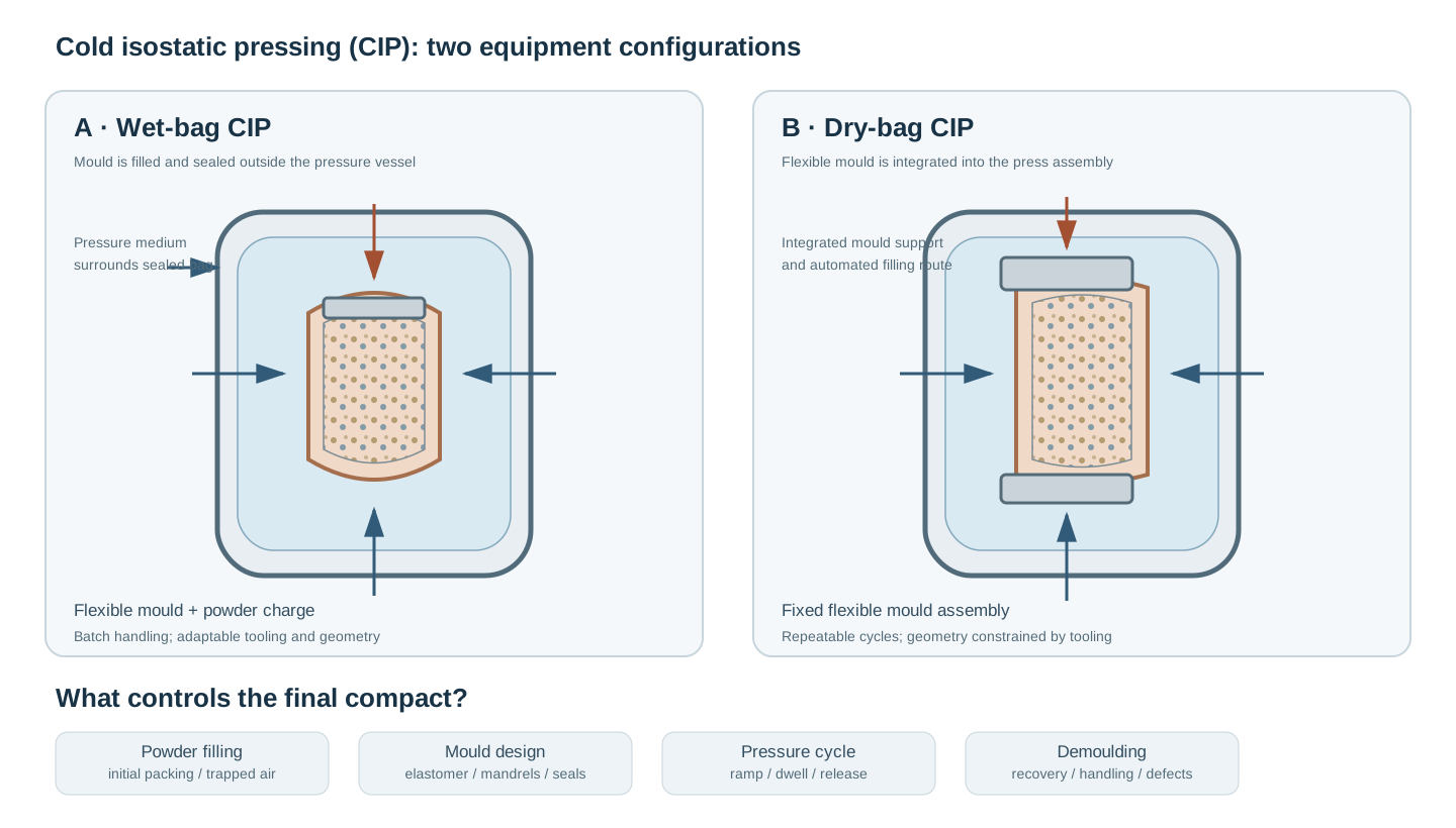
In wet-bag processing, the flexible mould is filled and sealed outside the pressure vessel. It is then placed inside the vessel and surrounded by the pressure-transmitting liquid.
Advantages - Flexible tooling and broad geometric adaptability. - Convenient for development work, prototypes and low-volume production. - Multiple moulds or components may be processed in one cycle, subject to vessel and tooling constraints. - Suitable for large preforms when the vessel and mould are appropriately designed.
Limitations - Manual handling and loading/unloading can increase cycle time. - Flexible mould deformation can limit dimensional precision. - Mould sealing and protection against fluid ingress are critical. - Repeated handling can introduce variation in filling and mould positioning.
3.2 Dry-bag CIP
In dry-bag processing, the flexible mould is fixed within the pressure vessel or its internal tooling. Powder filling takes place through an arrangement integrated with the press, allowing a more automated production cycle.
Advantages - Better potential for automated, repetitive production. - Reduced handling between filling and pressing. - Shorter cycle times can be achieved for suitable component geometries. - Particularly useful for relatively simple, repeatable shapes.
Limitations - Tooling is more integrated and less flexible than wet-bag tooling. - Geometry and mould access are constrained by the equipment design. - Local pressure-transfer conditions near mould supports or fixed regions require attention. - Initial tooling and equipment integration can be more demanding.
Neither method is universally superior. Wet-bag CIP is often selected for flexibility, while dry-bag CIP is attractive where production volume and repeatability justify dedicated tooling.
4. Pressure vessel and process equipment
A CIP system typically contains:
- Pressure vessel: a certified high-pressure enclosure designed for the maximum allowable working pressure and applicable safety code.
- Pressure-generation unit: a pump or intensifier that raises the pressure-medium pressure.
- Pressure medium: a compatible liquid selected for the vessel, seals, mould and pumping system.
- Flexible mould: an elastomeric container that encloses the powder.
- Mould closure and seals: prevent pressure-medium penetration and powder loss.
- Pressure measurement and control: calibrated instrumentation and a defined pressure-time cycle.
- Safety devices: overpressure protection, interlocks, guarded operation and controlled depressurization provisions.
The pressure vessel stores substantial energy. Equipment selection, inspection, maintenance and operation must follow the manufacturer’s procedures and applicable pressure-equipment regulations. A CIP vessel must never be treated as a general-purpose sealed container.
5. Powder requirements and mould filling
CIP reduces the influence of external rigid-die wall friction, but it does not remove the need for a well-designed feed powder.
Important powder attributes include: - Particle and agglomerate size distributions. - Granule morphology, strength and internal porosity. - Moisture and binder state. - Flowability and segregation tendency. - Initial bulk/tap density and packing reproducibility. - Compatibility with any mould-contact materials.
The powder should fill the mould reproducibly without large voids or segregation. For a long or complex mould, the filling route may create spatial variations before pressure is applied. A uniform external pressure cannot fully correct a poorly distributed initial powder bed.
Record powder mass, filling sequence, mould orientation, any vibration or settling procedure, and the method used to control trapped air.
6. Flexible mould design
Mould design is a central part of CIP process engineering. The mould must contain the powder, transmit pressure, accommodate deformation and release the compact without damaging it.
6.1 Elastomer selection
The elastomer must be compatible with the pressure medium, temperature, cleaning procedure and expected cyclic deformation. Relevant properties include: - Elastic modulus and nonlinear stress–strain response. - Reversible deformation and fatigue resistance. - Tear and abrasion resistance. - Chemical compatibility and swelling behaviour. - Permeability and sealing performance. - Dimensional stability over repeated cycles.
A mould material should not be selected from hardness alone. Its behaviour under the actual pressure, geometry and cycle history must be evaluated.
6.2 Mould geometry and dimensional compensation
The mould cavity is not necessarily identical to the target green-body dimensions. During compaction, the powder volume decreases while the elastomer changes shape. After unloading, both the elastomer and compact recover to some extent.
Dimensional compensation should therefore be based on measured compaction and recovery data for the actual powder–mould system. Do not assume isotropic shrinkage for every shape. Geometry, mandrels, local constraints and mould thickness can produce directional differences.
6.3 Mandrels and internal tooling
Rigid mandrels or inserts can define internal features, support the mould or produce hollow components. They also introduce local constraints and contact regions that can alter pressure transmission and compact density. Their geometry, surface finish, alignment and removal sequence should be considered during mould design.
7. Compaction mechanisms under isostatic loading
As pressure increases, powder densification may involve several overlapping mechanisms:
- Particle and granule rearrangement.
- Granule deformation and fragmentation.
- Collapse of larger interparticle voids.
- Increased particle contact area and local deformation.
- Development of a mechanically coherent green compact.
The sequence and relative importance depend on powder morphology, granule strength, binder, moisture and pressure history. A pressure increase may yield diminishing density gains after the readily collapsible void structure has been reduced.
CIP can produce a more uniform density distribution than conventional single-action pressing in many practical geometries because the external pressure is applied around the flexible mould. However, internal friction, initial filling variation, mould constraints and complex geometry can still produce density gradients.
8. Pressure, dwell and depressurization
The process is defined by a pressure-time history, not by a maximum pressure alone.
8.1 Pressurization
The pressure ramp should be compatible with the mould, seals, powder bed and equipment. An excessively aggressive ramp may amplify trapped-air effects, mould movement or local deformation. The appropriate ramp must be established for the system rather than copied as a universal value.
8.2 Dwell time
Dwell time is the interval at the selected pressure. It allows the system to reach the intended compaction state, but longer dwell does not necessarily produce a proportional density increase. Determine whether density, dimensions or green strength change meaningfully with dwell under the selected conditions.
8.3 Controlled depressurization
Depressurization is a critical stage. The elastomer can recover and detach from the compact in a nonuniform way. During this stage, changing contact conditions may impose local stresses on the green body and initiate cracks, particularly in complex shapes or near geometric transitions.
A controlled pressure-release schedule should be established from equipment guidance and experimental validation. Record the pressure-time profile, not merely the nominal maximum pressure.
9. Green density and dimensional assessment
The average green density is calculated from the compact mass and external volume:
[ _{}= ]
For a cylindrical compact:
[ V_{}=()^2h ]
Relative green density is:
[ D_{}= ]
The theoretical-density basis must match the actual composition and phase assemblage. State whether the mass includes binder, lubricant or residual moisture.
Average density alone cannot demonstrate spatial uniformity. Where density gradients matter, use sectioned measurements, validated local-density methods, dimensional mapping or a validated numerical model. Compare replicate compacts and document measurement uncertainty.
10. Green machining and post-pressing handling
CIP compacts may be produced as billets or near-net-shape preforms. Depending on green strength and geometry, machining can be used to establish features that are difficult to form directly in a flexible mould.
Green machining introduces its own risks: - Edge chipping and local fracture. - Damage around holes or thin sections. - Residual stress release. - Handling damage during transfer. - Moisture or binder changes during storage.
Select machining tools and support conditions based on measured green strength. Inspect the compact before and after machining, and define storage conditions that prevent uncontrolled moisture exchange or contamination.
11. Defects, mechanisms and diagnosis
| Defect | Possible mechanism | Diagnostic approach |
|---|---|---|
| Cracking during depressurization | Nonuniform elastomer recovery or mould–compact detachment stresses | Inspect crack location; review mould geometry and pressure-release profile |
| Low-density regions | Poor initial filling, trapped air, segregation or local mould constraints | Section or map density; review filling sequence and mould support |
| Shape distortion | Elastomer deformation, asymmetric tooling or nonuniform recovery | Compare mould and compact dimensions; inspect mandrel alignment |
| Fluid ingress / wet powder | Inadequate mould sealing, damaged elastomer or closure failure | Inspect seals, mould surface and post-cycle powder condition |
| Surface marking | Mould folds, seams, surface damage or trapped foreign material | Inspect mould interior and compact surface |
| Green-body fracture during demoulding | Insufficient green strength, undercuts or excessive demoulding force | Review powder condition, mould release and demoulding sequence |
| Cracks after green machining | Weak compact, machining load or pre-existing density variation | Examine fracture surfaces and machining support |
| Differential sintering shrinkage | Residual density or composition gradients in the green body | Compare green-state uniformity with fired dimensions and microstructure |
These associations are diagnostic hypotheses, not unique causes. Confirm them through controlled trials, cross-sections, density measurements and review of the full pressure cycle.
12. CIP compared with uniaxial die pressing
| Feature | Cold isostatic pressing | Uniaxial die pressing |
|---|---|---|
| Load transmission | Liquid pressure through flexible mould | Punch force through rigid die |
| External wall friction | Strongly reduced relative to rigid-die pressing | Can attenuate stress along the die wall |
| Density distribution | Often more uniform, but not perfectly uniform | Can show axial and radial gradients |
| Tooling | Flexible elastomer mould and pressure vessel | Rigid die and punches |
| Geometry | Good flexibility for billets and some complex preforms | Efficient for repeatable shapes compatible with punch/die motion |
| Dimensional precision | Often lower due to mould deformation and recovery | Generally better with well-designed rigid tooling |
| Production mode | Wet-bag for flexible/batch work; dry-bag for automated production | Highly suited to high-throughput automated production |
| Ejection | Demoulding from flexible mould | Ejection through the rigid die |
CIP may also be used as a post-compaction step after uniaxial pre-pressing. In that route, the preform is placed in a sealed flexible mould and subjected to isostatic pressure. The additional step can improve consolidation, but the initial pressing defects and density distribution must still be considered.
13. CIP versus hot isostatic pressing
CIP and hot isostatic pressing (HIP) are not interchangeable.
- CIP: generally near ambient temperature; liquid pressure medium; flexible mould; produces a green compact that normally requires subsequent thermal processing.
- HIP: elevated temperature and high gas pressure; used to densify encapsulated powders or close residual porosity in suitable components.
CIP forms a green body. It does not, by itself, eliminate all porosity or produce a fully dense ceramic.
14. Process development workflow
A disciplined development sequence is:
- Characterize powder flow, granules, moisture and initial packing.
- Select a mould concept based on component geometry and production scale.
- Verify elastomer and seal compatibility with the pressure medium.
- Establish repeatable mould filling and sealing.
- Define a conservative, equipment-approved pressure cycle.
- Evaluate pressure, dwell and depressurization effects separately.
- Measure green density, dimensions, green strength and defect frequency.
- Assess demoulding and any green machining.
- Validate downstream debinding and sintering.
- Reassess the process window using replicate batches and statistical variation.
Use a designed experiment when interactions among pressure, dwell, filling density and mould geometry are important. Avoid changing multiple uncontrolled factors between trials.
15. Safety and operational controls
CIP equipment is high-pressure equipment and must be operated only by trained personnel under approved procedures. The vessel, closures, seals, pressure lines, pump/intensifier and overpressure protection must be rated and maintained for the intended service.
Key controls include: - Never exceed the certified working pressure or bypass safety interlocks. - Inspect the vessel, closure, seals, hoses and mould before each cycle. - Keep personnel outside the defined exclusion zone during pressurization. - Do not open the vessel until the system confirms zero pressure. - Use the specified pressure medium and follow its handling and disposal requirements. - Treat leaks, abnormal pressure behaviour and unusual noises as stop-work conditions. - Follow the equipment manufacturer’s depressurization and maintenance procedures.
The compressed liquid and vessel contain stored energy. Improvised pressure vessels or unapproved mould closures are unacceptable.
16. Minimum reporting checklist
A reproducible CIP study should report:
- Powder composition/phase assemblage and particle/granule characteristics.
- Powder conditioning, moisture, binder/lubricant and initial fill density.
- Wet-bag or dry-bag configuration.
- Mould material, geometry, wall thickness, closure and seal design.
- Mandrels, inserts and other rigid tooling.
- Pressure-medium identity and compatibility considerations.
- Maximum pressure, pressurization rate, dwell time and depressurization profile.
- Mould orientation and filling procedure.
- Green mass, dimensions, density basis and measurement method.
- Green strength, demoulding behaviour and defect observations.
- Green machining and subsequent debinding/sintering conditions.
References
- P. E. Price, “Cold Isostatic Pressing,” in ASM Handbook, Volume 7: Powder Metallurgy (2015), pp. 255–259. https://doi.org/10.31399/asm.hb.v07.a0006074
- R. J. Henderson, H. W. Chandler, A. R. Akisanya, H. Barber and B. Moriarty, “Finite element modelling of cold isostatic pressing,” Journal of the European Ceramic Society 20 (2000), 1121–1128. https://doi.org/10.1016/S0955-2219(99)00280-0
- “Visualizing isostatic pressing of ceramic powders using finite element analysis,” Journal of the European Ceramic Society 26 (2006), 2265–2272. https://doi.org/10.1016/j.jeurceramsoc.2005.03.256
- Forschungszentrum Jülich, “Cold isostatic pressing,” Processing of Ceramics. https://apps.fz-juelich.de/ceramics/index.php?title=Cold_isostatic_pressing