Ceramic Tape Casting: Slurry Formulation, Green-Tape Processing and Lamination
Ceramic Tape Casting: Slurry Formulation, Green-Tape Processing and Lamination
Ceramic tape casting is a wet-forming process used to manufacture thin, flexible ceramic sheets known as green tapes. A ceramic powder is dispersed in a liquid medium with suitable organic additives. The resulting slurry is delivered beneath a doctor blade onto a moving carrier, dried, and released as a self-supporting sheet. The green tape can then be cut, punched, printed, stacked, laminated, debound and sintered.
Tape casting is widely used where planar ceramic layers, controlled thickness and multilayer construction are required. It is related to doctor-blade coating because both use a blade to meter a flowing material. The distinction is the feed and the objective: conventional tape casting creates a handleable ceramic green body with a substantial powder fraction and an organic binder system, rather than simply depositing a thin solution-derived coating.
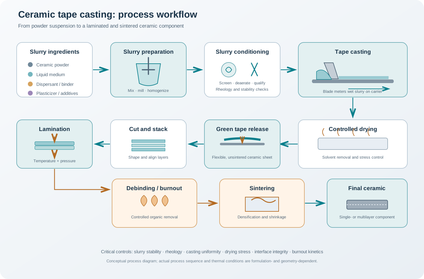
1. What makes a ceramic green tape?
A green tape is a shaped, unsintered ceramic body. It contains ceramic particles held together by an organic phase that provides enough cohesion and flexibility for handling and subsequent processing.
A typical conventional slurry contains:
- Ceramic powder: the inorganic solid phase that determines the final ceramic composition and much of its microstructure.
- Liquid medium: water or an organic solvent that provides a continuous phase for mixing and casting.
- Dispersant: helps stabilize the powder suspension and limit agglomeration.
- Binder: provides cohesion and green strength after drying.
- Plasticizer: modifies the mechanical response of the binder-rich organic phase, generally improving flexibility and reducing brittleness.
- Optional process additives: antifoaming agents, wetting agents, pore formers or other additives selected for a defined purpose.
These ingredients are not interchangeable. A dispersant primarily controls particle–particle interactions in the slurry; a binder forms the polymeric network that holds the dried tape together; and a plasticizer changes the mobility and mechanical response of the binder phase. An additive may influence more than one property, but its function should be identified from measurements rather than inferred from its name.
2. Slurry formulation: design by function
A robust tape-casting formulation is not obtained by selecting each additive independently. The ingredients interact. For example, a binder may adsorb on particle surfaces, a dispersant may compete for adsorption sites, and a plasticizer may alter binder solubility or the viscoelastic properties of the dried organic phase.
The formulation should therefore be designed around the desired process window: - stable suspension during storage and casting; - sufficiently high solids loading without unmanageable viscosity; - controlled flow through the blade region; - low bubble and agglomerate content; - uniform drying without cracking or warping; - adequate green strength and flexibility; - clean removal of organics during debinding.
2.1 Ceramic powder
The powder is the functional inorganic phase. Its characteristics influence packing, slurry viscosity, drying behaviour, green density and sintering.
Important powder descriptors include:
- particle-size distribution, including the coarse tail;
- primary-particle size versus agglomerate size;
- particle morphology and aspect ratio;
- specific surface area;
- surface chemistry and hydroxylation;
- moisture content;
- true density and batch-to-batch variation.
A broad particle-size distribution can sometimes improve packing, but it can also increase segregation or produce non-uniform local flow. A high specific surface area generally increases the amount of liquid and dispersant needed to wet and stabilize the powder. The optimum powder condition is therefore not defined by the smallest possible particle size; it is defined by the required packing, rheology and final microstructure.
2.2 Solvent or liquid medium
The liquid medium must wet the powder, support additive compatibility and provide a practical drying rate. Two broad approaches are used:
Water-based systems - avoid many of the flammability and volatile-organic-compound concerns associated with organic solvents; - can use water-soluble or water-dispersible binders and dispersants; - may require careful control of pH, ionic strength, powder surface chemistry and drying humidity; - can be unsuitable for powders that react adversely with water unless the surface chemistry or process is appropriately controlled.
Organic-solvent systems - can dissolve polymeric binders that are not readily compatible with water; - may offer faster drying or different wetting behaviour; - require solvent-compatible additives and suitable ventilation, vapour management, fire protection and exposure controls; - can be limited by solvent toxicity, flammability and environmental requirements.
Solvent selection should consider the entire process, not only the initial slurry viscosity. Solvent evaporation, binder solubility, drying stress, carrier compatibility and workplace safety all matter.
2.3 Dispersants
Dispersants reduce unwanted particle association and help maintain a uniform suspension. Depending on the system, stabilization may involve electrostatic repulsion, steric repulsion or a combination of both.
The dispersant must interact favourably with the powder surface in the chosen liquid medium. Its performance depends on: - powder surface chemistry and specific surface area; - pH and ionic strength in aqueous systems; - solvent polarity and additive solubility; - dispersant molecular structure and adsorption; - solids loading and mixing history.
Too little dispersant may leave agglomerates and produce high viscosity, poor packing or blade streaks. Excess dispersant may increase the concentration of free organic material, alter drying and burnout, or destabilize the suspension in some systems. A dispersant dose should be optimized experimentally rather than copied as a universal weight percentage.
Useful screening measurements include viscosity versus dispersant concentration, sedimentation or accelerated stability, particle-size distribution after dispersion, and zeta potential where the measurement is meaningful for the system.
2.4 Binders
The binder provides cohesion to the dried green tape. It helps the sheet survive carrier release, cutting, punching, handling and lamination.
Binder selection depends on: - solubility or dispersibility in the selected liquid medium; - compatibility with the dispersant and powder surface; - molecular weight and solution viscosity; - film-forming behaviour; - green tensile strength and elongation; - thermal decomposition and burnout characteristics.
Insufficient binder can produce weak, friable tapes that tear during release or handling. Excess binder can raise slurry viscosity, increase organic loading, promote drying stress and make debinding more difficult. Binder content must be balanced against the required green strength and the final thermal process.
2.5 Plasticizers
Plasticizers modify the mechanical behaviour of the binder-rich phase. They generally increase chain mobility and reduce brittleness, although the effect depends on polymer chemistry, plasticizer compatibility and concentration.
A useful plasticizer should: - be compatible with the binder; - remain sufficiently uniform during drying and storage; - provide the required flexibility without making the tape tacky or weak; - avoid excessive migration or exudation; - have a thermal removal profile compatible with the debinding cycle.
Too little plasticizer may leave a brittle tape. Too much may reduce green strength, increase tack, promote deformation during handling or cause phase separation. The binder-to-plasticizer ratio is therefore a key formulation variable, but there is no universal optimum ratio.
2.6 Other additives
Antifoaming agents can reduce persistent bubbles, but an unsuitable additive may create surface defects or interfere with wetting. Pore formers are used when a controlled porous structure is required; their particle size, distribution and burnout behaviour must be considered. Release agents and wetting modifiers may be useful for particular carrier and slurry combinations.
Additives should be included only when a defined process problem or final-material requirement justifies them. Every additional organic component increases formulation complexity and may affect drying, debinding and residual porosity.
3. Solids loading and slurry composition
Solids loading is commonly expressed as a mass fraction or volume fraction. These quantities are not interchangeable.
The solids mass fraction is:
[ w_s= ]
where (m_s) is the ceramic-powder mass, (m_l) is the liquid-medium mass and (m_a) is the mass of non-ceramic additives included in the stated basis. Some laboratories define solids loading by excluding selected dissolved organics, so the reporting convention must be explicit.
The ceramic volume fraction can be estimated from the constituent masses and densities:
[ _c= ]
where the summation includes the phases included in the chosen volume-fraction definition. For a slurry, the ceramic volume fraction is often more directly related to particle crowding and flow than the ceramic mass fraction.
Higher ceramic loading can reduce drying shrinkage and the amount of liquid that must be removed. However, it also increases particle interactions and may raise viscosity sharply, especially near a packing limit. The practical optimum is a balance between high green density and a slurry that can still be mixed, deaerated, delivered and cast uniformly.
When reporting a formulation, state whether additive quantities are based on powder mass, total slurry mass, solvent mass or polymer mass. Without the basis, a numerical formulation is not reproducible.
4. Mixing, milling and slurry conditioning
A common process sequence is:
- Powder inspection and conditioning: check moisture, agglomeration and batch identity.
- Liquid and dispersant preparation: dissolve or disperse the dispersant in the selected medium under controlled conditions.
- Powder incorporation: add the powder gradually while maintaining effective mixing.
- Deagglomeration: use an appropriate milling or high-shear mixing operation to break soft agglomerates without introducing unacceptable contamination or damaging the powder.
- Binder addition: introduce the binder using a sequence compatible with its dissolution and adsorption behaviour.
- Plasticizer addition: add and homogenize the plasticizer according to its compatibility with the binder phase.
- Final homogenization: establish uniform composition and rheology.
- Filtration or screening: remove foreign particles and large agglomerates when compatible with the intended particle-size distribution.
- Deaeration: remove entrained bubbles before casting.
- Slurry qualification: measure rheology, stability, density and, where appropriate, particle-size distribution.
The sequence is formulation-dependent. For example, adding a polymer too early can increase viscosity and make deagglomeration inefficient. Conversely, an unsuitable late addition may not distribute uniformly. The mixing order should be justified by the chemistry and verified by repeatable measurements.
4.1 Milling and contamination control
Milling is used to break agglomerates and homogenize the suspension. The milling media, vessel lining, milling energy and duration must be selected to avoid introducing contaminants that affect the final ceramic.
A smaller measured particle size after milling does not necessarily mean the powder has been improved. The process may have fractured particles, changed surface chemistry or introduced wear debris. Compare particle-size distributions, phase composition where relevant and contamination indicators before and after milling.
4.2 Deaeration
Entrained bubbles can produce pinholes, blisters, local thickness variation and defects that later become crack-initiation sites. Vacuum deaeration is widely used, but it must be controlled to avoid excessive foaming or solvent loss. The slurry should be allowed to recover to a stable condition before casting if vacuum exposure changes its temperature or structure.
5. Rheology: the central process-control variable
Tape-casting slurry is usually a concentrated suspension and may exhibit non-Newtonian behaviour. The viscosity measured at one shear rate is not sufficient to describe its behaviour in the reservoir, blade gap and deposited tape.
5.1 Shear thinning
Many ceramic slurries show shear-thinning behaviour: apparent viscosity decreases as shear rate increases. This can help the slurry flow through the blade region while retaining a higher low-shear viscosity that limits sedimentation. However, excessive structural breakdown or slow recovery can lead to thickness variation after casting.
A simple power-law approximation is:
[ =K^{n} ]
and
[ _{app}=K^{n-1} ]
where () is shear stress, () is shear rate, (K) is the consistency index, (n) is the flow index and (_{app}) is apparent viscosity. For (n<1), the model represents shear-thinning behaviour over the fitted range.
This model does not capture every slurry. Yield stress, thixotropy, viscoelasticity and time-dependent recovery may require additional characterization or more appropriate constitutive models.
5.2 Thixotropy and recovery
A thixotropic slurry loses structure under shear and rebuilds it with time after shear is reduced. Some structural recovery can be useful after the slurry passes beneath the blade, but recovery that is too slow may permit sedimentation or surface flow. Recovery that is too rapid may interfere with leveling.
A three-interval thixotropy test can be used to examine low-shear structure, high-shear breakdown and subsequent recovery. Report the shear rates, durations, temperature and rest protocol; a single hysteresis loop is not a complete quantitative description of thixotropy.
5.3 Rheology measurements
For a meaningful slurry qualification, consider: - flow curves over a shear-rate range relevant to the process; - up/down sweeps to assess hysteresis; - oscillatory measurements where viscoelastic structure is important; - time-dependent recovery after high shear; - temperature dependence; - density and sedimentation stability.
Avoid comparing viscosity values measured with different spindle geometries, gaps, shear rates or temperature histories as if they were directly equivalent.
6. Casting and wet-tape formation
In a continuous tape caster, the slurry is delivered to a reservoir ahead of the doctor blade. A moving carrier passes beneath the blade and transports the wet layer into a drying zone. In a batch caster, the casting head may move across a stationary substrate.
Important process variables include: - blade gap and blade alignment; - carrier speed; - slurry head and feed stability; - blade geometry and width; - slurry rheology and temperature; - carrier surface energy and release behaviour; - cleanliness and flatness of the carrier.
The wet thickness is influenced by the blade geometry and the flow field. It should not be assumed to equal the blade gap. The dried green-tape thickness is further reduced by solvent removal and packing changes.
A stable coating bead and uniform slurry delivery are required across the casting width. Blade misalignment can produce a transverse thickness gradient. Particles or agglomerates trapped beneath the blade can generate longitudinal grooves or streaks.
7. Drying: solvent transport and stress development
Drying converts the wet layer into a self-supporting green tape. Solvent evaporates from the exposed surface and must be transported from the interior toward that surface. If evaporation is too rapid relative to internal transport, concentration and shrinkage gradients develop.
Potential consequences include: - surface skin formation; - internal stress and cracking; - warping or curling; - wrinkling and surface texture defects; - delamination from the carrier; - non-uniform residual solvent.
Drying is therefore a coupled heat- and mass-transfer problem, not simply a waiting period after casting.
7.1 Why drying cracks form
As solvent is removed, particles approach one another and the organic phase develops a load-bearing network. Capillary forces and constrained shrinkage can generate tensile stresses. Cracks form when local stress exceeds the evolving strength of the green body.
Stress can be amplified by: - excessive wet thickness; - rapid or non-uniform surface evaporation; - poor particle packing; - agglomerates and entrained bubbles; - insufficient or incompatible binder; - unsuitable plasticizer level; - poor carrier release or non-uniform adhesion.
7.2 Controlling drying
Possible controls include: - reducing the wet thickness per pass; - moderating airflow and temperature; - controlling relative humidity for water-based systems; - using a staged drying profile; - ensuring uniform airflow across the tape width; - optimizing solids loading and particle packing; - balancing binder and plasticizer; - maintaining a stable carrier surface.
A slower drying schedule is not automatically better: excessive drying time can reduce throughput and may permit sedimentation or other time-dependent changes before the structure is fixed. The goal is controlled, sufficiently uniform solvent removal.
8. Green-tape release and characterization
After drying, the tape is separated from the carrier. Release quality depends on carrier surface properties, tape strength, drying history and residual stress.
A useful green-tape qualification includes:
- thickness and thickness uniformity;
- mass per unit area;
- apparent green density;
- flexibility and tensile behaviour;
- surface roughness and visible defects;
- residual solvent where relevant;
- dimensional stability after release;
- handling performance during cutting and punching.
Green density can be estimated from the tape mass, area and thickness, but the interpretation depends on whether the tape contains organic additives and whether its volume includes surface roughness or open pores. Report the calculation basis.
9. Cutting, punching and multilayer lamination
Green tapes can be cut or punched before stacking. These operations require sufficient green strength and dimensional stability. Fine features may be damaged by brittle fracture, tool wear or local deformation.
9.1 Stacking and alignment
For a multilayer component, individual tapes are aligned and stacked. Registration errors can accumulate through the stack. The tapes may also contain printed or patterned features, which impose additional constraints on alignment, surface cleanliness and lamination flow.
9.2 Thermocompression lamination
Thermocompression joins the layers using controlled temperature and pressure. The binder-rich phase softens or becomes sufficiently mobile to establish contact and bond adjacent tapes.
The process window must provide adequate interlayer bonding without excessive lateral flow, feature distortion or trapped voids. Important variables include: - lamination temperature; - pressure and pressure uniformity; - dwell time; - tape organic content and viscoelastic response; - surface condition and cleanliness; - stack thickness and alignment.
A poorly bonded interface can remain as a delamination plane during debinding or sintering. Excessive pressure or temperature can distort cavities, channels or printed features.
9.3 Alternative joining strategies
Depending on the design, multilayers can be produced by sequential casting, thermocompression, adhesive-assisted joining or other specialized approaches. These routes differ in interface chemistry, organic content and the risk of introducing a residual interlayer. They should not be treated as equivalent without checking the final interface and thermal compatibility.
10. Debinding: removing the organic phase
The green tape contains organics that must be removed before densification. Debinding, also called binder burnout, converts or volatilizes the organic components and allows gaseous products to escape from the body.
This is a critical stage because the green body has limited permeability and mechanical strength. If gas is generated faster than it can escape, internal pressure can cause: - cracks; - blisters; - delamination between layers; - warping; - bloating or local distortion; - residual carbon or other unwanted residues if conversion is incomplete.
10.1 Build a schedule from thermal analysis
Thermogravimetric analysis (TGA), preferably combined with differential scanning calorimetry (DSC), can identify mass-loss regions and thermal events for the actual organic formulation. These data help define candidate heating and holding regions.
The final schedule must also consider: - sample thickness and geometry; - green density and permeability; - binder and plasticizer chemistry; - atmosphere and gas flow; - heating rate and furnace loading; - diffusion distance for decomposition products; - compatibility with any internal functional layers or electrodes.
A schedule copied from another formulation is not automatically safe. Even when the same binder family is used, changes in molecular weight, plasticizer content, solids loading and laminate thickness can alter gas-release behaviour.
10.2 Why slow heating may be necessary
Slow heating through major decomposition intervals can limit the rate of gas generation and reduce internal pressure. However, the appropriate heating rate and hold times must be derived from thermal analysis and validated on representative specimens. The thickest or most densely laminated geometry is often more demanding than a thin single tape.
11. Sintering and dimensional change
After debinding, the remaining ceramic compact is heated to develop the required bonding and density. Sintering causes shrinkage as pores are eliminated or reduced and particles form a connected microstructure.
Tape-cast bodies may exhibit anisotropic dimensional change because the green structure can contain direction-dependent particle orientation, pore distribution and packing. The casting direction, thickness direction and in-plane directions should therefore be considered separately when measuring shrinkage.
For a measured dimension, linear shrinkage is:
[ S_L=% ]
where (L_g) is the green or pre-sintering dimension at the defined reference stage and (L_f) is the final dimension. State whether the reference dimension is measured before or after debinding, because organic removal can itself produce dimensional change.
For multilayer structures, mismatch in shrinkage or thermal expansion between layers can lead to curvature, interfacial stress or cracking. Co-sintering therefore requires compatible shrinkage behaviour and thermal processing windows.
12. Common defects and diagnostic approach
| Defect | Possible origin | Diagnostic direction |
|---|---|---|
| Longitudinal grooves or streaks | Blade contamination, trapped agglomerates, unstable slurry feed | Inspect blade and carrier; examine slurry dispersion and coarse particle tail |
| Transverse thickness gradient | Blade not parallel to carrier, non-uniform gap or carrier flatness | Map wet and dry thickness across the width |
| Pinholes and bubbles | Entrained air, foaming or gas release | Check deaeration, slurry handling and additive compatibility |
| Sedimentation or composition gradient | Insufficient suspension stability or excessive delay before casting | Measure stability and rheology as a function of time |
| Mud-crack pattern | Excessive drying stress or high wet loading | Reduce wet thickness and moderate drying gradients |
| Centre or longitudinal cracks | Local inhomogeneity, bubbles, agglomerates or stress concentration | Inspect defect initiation sites and drying uniformity |
| Wrinkling or orange-peel texture | Surface drying too rapidly relative to internal solvent transport | Adjust airflow, temperature and humidity |
| Curling or warping | Through-thickness drying gradient or asymmetric stress | Compare both surfaces and drying conditions |
| Tape tears during release | Low green strength, poor binder network or excessive carrier adhesion | Review binder/plasticizer balance and carrier release |
| Brittle tape | Insufficient plasticization or incompatible binder system | Measure tensile response and assess organic-phase compatibility |
| Sticky or excessively soft tape | Excess plasticizer, residual solvent or unsuitable binder | Check composition and drying completion |
| Lamination delamination | Inadequate bonding, contamination, trapped air or unsuitable lamination window | Inspect interfaces and optimize temperature/pressure/time |
| Blistering during debinding | Gas generation faster than gas escape | Use TGA/DSC and reduce thermal severity through decomposition regions |
| Cracks after debinding | Internal pressure, weak green interfaces or non-uniform burnout | Compare single-layer and laminated specimens; inspect thermal schedule |
| Warping after sintering | Differential shrinkage, density gradients or layer mismatch | Measure directional shrinkage and examine cross-sections |
Defect diagnosis should follow the process sequence. A crack visible after sintering may have originated during drying, lamination or debinding. Examine intermediate-stage specimens rather than assigning every final defect to the sintering step.
13. Process-development workflow
A disciplined development plan separates slurry optimization from casting, drying and thermal processing.
Stage A — Powder and additive qualification 1. Characterize powder size distribution, morphology, surface area and moisture. 2. Screen dispersant compatibility and dose. 3. Select solvent and binder based on solubility, safety and powder compatibility. 4. Screen plasticizer compatibility and binder/plasticizer balance.
Stage B — Slurry optimization 5. Establish a solids-loading range. 6. Optimize mixing and deagglomeration. 7. Measure flow curves, stability and time-dependent recovery. 8. Filter or screen where appropriate and deaerate.
Stage C — Casting and drying 9. Calibrate blade gap and carrier speed. 10. Map wet and dry thickness across the tape. 11. Screen drying conditions while keeping slurry composition fixed. 12. Evaluate release, flexibility, tensile strength and defect density.
Stage D — Multilayer and thermal processing 13. Establish cutting and alignment procedures. 14. Optimize lamination using interface integrity and dimensional fidelity as responses. 15. Use TGA/DSC to design a candidate debinding schedule. 16. Validate burnout on representative thicknesses and laminate geometries. 17. Optimize sintering and measure directional shrinkage and final density.
Use a designed experiment where practical. Change a limited set of variables at a time or use a structured design that can resolve interactions. Do not simultaneously alter solids loading, dispersant, binder, plasticizer and drying conditions; the resulting data will not identify the cause of improvement or failure.
14. Characterization and quality control
| Stage | Measurement | Purpose |
|---|---|---|
| Powder | Laser diffraction, microscopy, surface-area measurement, moisture analysis | Establish powder condition and batch consistency |
| Slurry | Rheometry, density, sedimentation, particle-size analysis | Confirm processability and suspension stability |
| Wet tape | Wet thickness, optical inspection, mass per area | Monitor casting uniformity |
| Dried green tape | Thickness mapping, density, tensile/flexural handling tests, microscopy | Verify green-sheet quality |
| Laminate | Cross-sectional microscopy, interface inspection, dimensional mapping | Detect voids and delamination |
| Debinding | TGA/DSC, mass change, visual inspection | Verify organic removal and thermal schedule |
| Sintered tape | Density, shrinkage, porosity, microscopy, phase analysis | Assess final structure and dimensional stability |
For multilayer parts, cross-sectional inspection is particularly important. Surface inspection alone cannot establish that internal interfaces are free of voids or delamination.
15. Safety and environmental considerations
Tape casting combines fine ceramic powders, organic polymers and sometimes volatile or flammable solvents. Risk controls should be selected from the actual material safety data sheets and the laboratory’s approved procedures.
Key considerations include: - local exhaust ventilation for powders and solvent vapours; - appropriate respiratory and skin protection based on risk assessment; - combustible-dust controls for fine powders; - ignition-source control when using flammable solvents; - compatible storage and waste segregation; - safe handling of milling equipment and vacuum systems; - furnace exhaust management during binder burnout; - prevention of exposure to decomposition products.
Water-based processing can reduce some solvent hazards, but it does not remove all risks. Powder inhalation, additives, microbial stability, drying energy and waste streams still require attention.
16. Minimum reporting checklist
For reproducibility, report:
- powder identity, batch, particle-size distribution and surface area;
- solvent identity and quantity;
- dispersant, binder and plasticizer identities and quantities;
- the basis used for every additive percentage;
- ceramic solids loading as mass fraction and, where possible, volume fraction;
- mixing order, equipment, speed, time and milling media;
- filtration and deaeration procedures;
- slurry density, temperature, rheology and stability;
- casting-head geometry, blade gap, carrier type and speed;
- drying temperature, airflow and relative humidity;
- wet and dry tape thickness and mapping positions;
- green-tape density and mechanical handling properties;
- cutting and lamination conditions;
- TGA/DSC data and debinding atmosphere/schedule;
- sintering schedule and directional shrinkage;
- final density, porosity, microstructure and defect inspection.
References
- M. Jabbari, R. Bulatova, A. I. Y. Tok, C. R. H. Bahl, E. Mitsoulis and J. H. Hattel, “Ceramic tape casting: A review of current methods and trends with emphasis on rheological behaviour and flow analysis,” Materials Science and Engineering: B 212 (2016), 39–61. https://doi.org/10.1016/j.mseb.2016.07.011.
- H. Ren et al., “The tape casting process for manufacturing low-temperature co-fired ceramic green sheets: A review,” Journal of the American Ceramic Society (2018). https://doi.org/10.1111/jace.15694.
- D. Hotza and P. Greil, “Review: Aqueous tape casting of ceramic powders,” Materials Science and Engineering: A 202 (1995), 206–217. https://doi.org/10.1016/0921-5093(95)09785-6.
- J. A. Lewis, K. A. Blackman, A. L. Ogden, J. A. Payne and L. F. Francis, “Rheological Property and Stress Development during Drying of Tape-Cast Ceramic Layers,” Journal of the American Ceramic Society 79 (1996), 3225–3234. https://doi.org/10.1111/j.1151-2916.1996.tb08099.x.
- J. Bauer et al., “Stress Development During Drying of Aqueous Zirconia Based Tape Casting Slurries Measured by Transparent Substrate Deflection Method,” Journal of the American Ceramic Society (2009). https://doi.org/10.1111/j.1551-2916.2009.03000.x.
- “Effects of Slurry Properties on the Crack Formation in Ceramic Green Sheets during Drying,” Journal of the Ceramic Society of Japan 114 (2006), 823–828. https://doi.org/10.2109/jcersj.114.823.
- Z. Fu and A. Roosen, “Shrinkage of Tape Cast Products During Binder Burnout,” Journal of the American Ceramic Society 98 (2015), 20–29. https://doi.org/10.1111/jace.13270.
- D. Hotza et al., “Tape casting of preceramic polymers toward advanced ceramics: A review,” International Journal of Ceramic Engineering & Science (2019). https://doi.org/10.1002/ces2.10009.
- K. Y. Javan and V. M. Sglavo, “Influence of drying conditions and plasticizer-to-binder ratio on the water-based tape casting of ceramic tapes,” International Journal of Applied Ceramic Technology 21 (2024), 1482–1492. https://doi.org/10.1111/ijac.14691.
- “New lamination technique to join ceramic green tapes for the manufacturing of multilayer devices,” Journal of the European Ceramic Society 21 (2001), 1993–1996. https://doi.org/10.1016/S0955-2219(01)00158-3.
Important process distinction: Tape casting is a green-body forming route. Doctor-blade coating of a solution-derived film does not necessarily involve a concentrated ceramic powder suspension, a polymeric green-strength network, lamination or binder burnout. The shared blade geometry should not obscure these differences.