Ceramic Injection Moulding: Feedstock Design, Rheology, Mould Filling and Debinding
Ceramic Injection Moulding: Feedstock Design, Rheology, Mould Filling and Debinding
Ceramic injection moulding (CIM), also described as ceramic powder injection moulding (C-PIM), is a near-net-shape forming route for producing small or medium-sized ceramic components with complex geometries and repeatable dimensions. It combines powder processing with thermoplastic shaping: a concentrated ceramic powder is dispersed in a temporary organic binder, the resulting feedstock is injected into a mould, and the binder is removed before sintering.
The process is not simply polymer injection moulding with ceramic added. The ceramic powder must remain uniformly distributed throughout mixing, injection, debinding and densification. Binder removal creates a fragile porous body, and the final dimensions depend on powder packing, debinding history and sintering shrinkage.
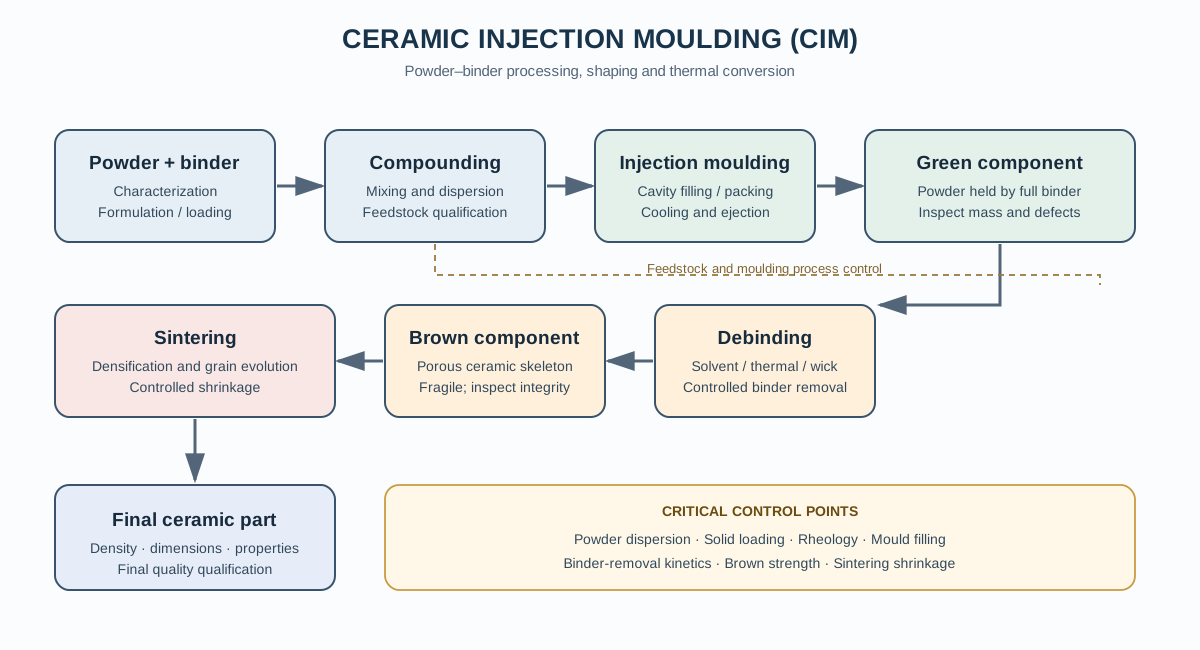
1. Process architecture and terminology
A conventional high-pressure CIM route consists of:
- Ceramic powder characterization and conditioning.
- Binder-system selection and feedstock formulation.
- Melt compounding and homogenization.
- Granulation or pellet preparation, where required.
- Injection into a temperature-controlled mould.
- Cooling and demoulding to obtain the green part.
- Debinding to remove the organic constituents and obtain the brown part.
- Sintering to develop the required density and microstructure.
- Dimensional, microstructural and functional inspection.
The green part contains the ceramic powder and essentially the complete binder system. The brown part is the powder compact after binder removal; it is porous and mechanically fragile. Sintering then consolidates the powder skeleton.
High-pressure CIM (HPIM) uses a heated, highly filled thermoplastic feedstock and an injection unit comparable in principle to polymer moulding equipment. Low-pressure injection moulding (LPIM) uses a lower-viscosity feedstock, commonly with a different binder chemistry and lower injection pressure. LPIM should not be treated as an interchangeable machine setting: its feedstock design, mould-filling behaviour and debinding route can differ substantially.
2. Ceramic powder requirements
Powder properties determine both the maximum achievable solid loading and the stability of the feedstock. Relevant characteristics include:
- Particle-size distribution, including coarse tails and fines.
- Particle morphology, aspect ratio and surface roughness.
- Specific surface area and surface chemistry.
- Agglomeration tendency and the effectiveness of deagglomeration.
- True density and batch-to-batch consistency.
- Moisture and adsorbed surface species.
Fine powders can improve sintering activity, but their high specific surface area increases binder demand and often raises feedstock viscosity. A broad or multimodal particle-size distribution may improve packing when appropriately designed, but it can also increase segregation risk if particle populations differ strongly in size, density or surface chemistry.
Powder drying and storage must be controlled where moisture affects powder–binder interactions, additive stability or melt processing. Drying conditions should be selected from the powder and binder specifications rather than adopted as a universal temperature–time recipe.
3. Binder-system architecture
The binder is a temporary processing medium. It must provide flow during injection, sufficient green strength after cooling, and a controlled pathway for removal without damaging the ceramic skeleton.
A multicomponent binder system commonly contains:
| Component | Primary function |
|---|---|
| Backbone polymer | Maintains green-part integrity and shape during handling and early debinding |
| Low-molecular-weight binder or wax | Reduces melt viscosity and may be selectively extracted |
| Plasticizer | Adjusts flexibility and flow behaviour |
| Lubricant / surfactant | Modifies friction and powder–binder interactions |
| Dispersing or coupling additive | Helps control powder agglomeration and interfacial compatibility |
Not every formulation requires every component. The chemistry and proportion of each constituent must be compatible with the powder surface, processing temperature, extraction medium and thermal-decomposition route.
A useful design principle is to create a continuous, mechanically effective binder phase while keeping the organic fraction as low as practical. Excess binder increases the amount that must be removed and can increase shrinkage or defect risk. Too little binder can cause poor flow, incomplete mould filling, excessive pressure, powder–binder separation and weak green parts.
3.1 Solid loading and critical loading
Solid loading is normally reported as a volume fraction, not merely as a mass percentage:
[ _s = ]
where (V_s) is the ceramic-powder volume and (V_b) is the binder-system volume. For a powder–binder mixture with known masses and densities:
[ _s = {m_s/_s+m_b/_b} ]
Here, (m_s) and (m_b) are the powder and binder masses, and (_s) and (_b) are their respective densities. The calculation assumes that the component volumes are additive; actual feedstock density should be measured when volume contraction or non-ideal mixing is significant.
The critical solid loading is the loading beyond which the feedstock can no longer be processed reliably because particle contacts and interparticle friction cause a steep rise in viscosity or loss of flow. The practical operating loading is normally below the experimentally determined critical value. It must be established for the specific powder, binder and mixing history.
High solid loading is desirable because it reduces the organic volume to be removed and can improve the packing of the brown body. However, maximizing loading without regard to rheology is not a sound optimization strategy.
4. Feedstock preparation and homogenization
Feedstock preparation is a critical operation, not simply a preliminary mixing step.
A typical sequence is:
- Verify powder identity, moisture, particle-size distribution and batch condition.
- Prepare and, where appropriate, pre-mix the binder constituents.
- Introduce powder progressively into the softened binder.
- Apply controlled shear and temperature to distribute the powder.
- Continue mixing until torque or another process indicator reaches a stable condition.
- Inspect the feedstock for agglomerates, unmixed regions and evidence of degradation.
- Granulate or pelletize the homogenized feedstock when required by the injection unit.
Internal batch mixers and twin-screw compounding systems are common approaches. The choice depends on batch size, feedstock viscosity, thermal sensitivity and the required level of compositional consistency.
Mixing temperature must be high enough to establish binder flow but low enough to avoid premature degradation. Excessive shear or residence time can also degrade polymers. Torque, temperature, mixing time and feedstock appearance should be recorded together; torque alone does not prove homogeneity.
Feedstock homogeneity should be assessed at more than one length scale. Powder-rich and binder-rich regions can be difficult to identify from a single bulk measurement. Microscopy, thermal analysis, density measurements and rheological consistency can provide complementary evidence.
5. Rheology and feedstock qualification
CIM feedstocks are highly filled suspensions with strong temperature- and shear-rate-dependent behaviour. They are generally non-Newtonian, and their apparent viscosity often decreases as shear rate increases.
A power-law approximation may be used over a defined shear-rate range:
[ = K^{n-1} ]
where () is apparent viscosity, (K) is the consistency index, () is shear rate and (n) is the flow-behaviour index. For shear-thinning behaviour, (n<1). This empirical expression should not be extrapolated outside the measured range or treated as a complete description of a highly filled feedstock.
Useful rheological measurements include:
- Apparent viscosity as a function of shear rate.
- Viscosity as a function of temperature.
- Repeatability after controlled thermal and shear histories.
- Time-dependent changes that may indicate degradation or structural evolution.
- Capillary or slit-die measurements where high-shear processing conditions need to be approximated.
A suitable feedstock should flow sufficiently to fill the cavity and reproduce fine features, but it must not become so fluid that powder–binder separation, flash formation or poor green-part stability becomes likely.
5.1 Powder–binder separation
During mould filling, the powder and binder experience velocity gradients and shear. If the formulation or flow geometry is unsuitable, the two phases can separate. Binder-rich films may develop near mould walls or at internal interfaces, while powder-rich regions form elsewhere.
Possible consequences include:
- Local variations in green density.
- Weak interfaces and delamination.
- Non-uniform debinding and pore structure.
- Differential sintering shrinkage.
- Distortion or cracking in the final component.
The risk is affected by powder loading, particle-size distribution, binder compatibility, feedstock rheology, gate design and injection conditions. A visually complete mould fill does not guarantee a homogeneous green part.
6. Injection unit, mould design and filling
The feedstock is heated to a controlled processing temperature and injected into a mould cavity through a feed system that commonly includes a nozzle, sprue, runner and gate. The cavity must be designed for the feedstock’s rheology and the component geometry.
Important design and process variables include:
- Injection temperature and mould temperature.
- Injection velocity and pressure profile.
- Gate position, gate dimensions and runner balance.
- Venting and the escape of displaced air.
- Wall thickness, flow length and abrupt section changes.
- Holding pressure and cooling time.
- Ejection geometry and green-part support.
A gate that is too restrictive can cause excessive pressure drop, shear heating or incomplete filling. Poor venting can trap gas and produce voids or surface defects. Large changes in wall thickness can create non-uniform cooling and differential shrinkage.
The mould should avoid unnecessary abrupt transitions and should provide balanced flow paths. For multi-cavity tooling, cavity-to-cavity consistency must be assessed rather than assumed.
6.1 Injection process window
The process window is established experimentally for each feedstock–mould combination. Increasing injection temperature can reduce viscosity, but excessive temperature or residence time can degrade the binder. Increasing injection speed can improve filling in some geometries, but may increase shear gradients and phase-separation risk.
Holding pressure can compensate for feedstock contraction before the gate freezes, but excessive packing may generate residual stresses or local density differences. Cooling must be sufficient for safe ejection without creating avoidable cycle time or thermal gradients.
Record the actual melt temperature, mould temperature, injection pressure, velocity profile, holding conditions and cycle time. Machine set points alone may not represent the temperature and pressure experienced by the feedstock inside the cavity.
7. Green-part inspection
Before debinding, inspect the green part for:
- Short shots and incomplete feature replication.
- Flash and parting-line defects.
- Weld or knit lines.
- Sink marks and surface irregularities.
- Voids, cracks and visible delamination.
- Ejection marks and handling damage.
- Mass and dimensional variation.
Green density and mass are useful process-control indicators, but neither independently proves internal homogeneity. For critical components, sectioning, microscopy or X-ray computed tomography can reveal internal defects and density-related features.
Sprues and runners may be recyclable in some production systems, but regrinding and reprocessing can alter binder condition and feedstock rheology. Recycled feedstock should be qualified against the same acceptance criteria as fresh material.
8. Debinding: the most sensitive process stage
Debinding removes the organic binder while preserving the geometry and connectivity of the ceramic-particle skeleton. It is often the rate-limiting stage of CIM because volatile products must escape through a developing pore network without generating damaging internal pressure or excessive stress.
The route depends on binder chemistry and component geometry. Common approaches include:
8.1 Solvent debinding
A soluble binder fraction is extracted using a compatible liquid. Extraction creates interconnected pores that can provide pathways for later removal of the remaining binder.
The solvent must selectively remove the intended component without swelling, dissolving or weakening the backbone polymer excessively. Extraction rate depends on solvent compatibility, temperature, time, exposed surface area, part thickness and pore connectivity.
Measure mass loss and, where appropriate, dimensional change. A fixed extraction time should not be assumed to indicate complete binder removal for every geometry.
8.2 Thermal debinding
The remaining organic constituents are decomposed or volatilized under a controlled atmosphere and heating schedule. The atmosphere may be inert, oxidizing or otherwise specified by the binder chemistry and ceramic system.
The heating rate is particularly important in temperature intervals where binder decomposition is rapid. If volatile generation exceeds the rate at which gases can escape, internal pressure can produce cracks, blisters or delamination.
Thermogravimetric analysis (TGA), preferably supported by differential scanning calorimetry (DSC), helps identify mass-loss stages and thermal events. The actual debinding schedule should be developed using representative parts and validated for the maximum section thickness and geometry.
8.3 Wick or capillary-assisted debinding
In wick debinding, a compatible porous surrounding medium absorbs a mobile binder fraction by capillary action. It can support the component and provide a route for binder transport. Its effectiveness depends on the binder’s wetting behaviour, pore structure and thermal history.
8.4 Catalytic and other chemical routes
Some binder systems are designed for catalytic or chemically assisted removal. Such routes require a binder chemistry and process environment specifically developed for that purpose. They should not be generalized to conventional wax/polymer binder systems.
8.5 Debinding defects and their causes
| Defect | Possible mechanism | Process checks |
|---|---|---|
| Internal cracking | Volatile generation or thermal stress exceeds the body’s ability to relax or vent | TGA/DSC, heating rate, atmosphere, part thickness |
| Blistering | Gas accumulation beneath a low-permeability surface region | Binder-removal sequence, venting pathways, surface condition |
| Slumping or distortion | Loss of binder support before the ceramic skeleton can retain shape | Backbone removal profile, support arrangement, temperature uniformity |
| Delamination | Feedstock separation or weak interfaces become exposed during binder removal | Mixing quality, mould filling, weld-line and interface inspection |
| Residual carbon | Incomplete oxidation or decomposition under an unsuitable atmosphere | Atmosphere, dwell, off-gas and mass-loss verification |
| Non-uniform porosity | Non-uniform powder packing or binder distribution | Feedstock homogeneity, sectioned microscopy, CT where appropriate |
Debinding schedules must be designed for the actual binder system and geometry. Published heating rates and temperatures are material-specific examples, not universal operating instructions.
9. Sintering and dimensional compensation
After debinding, the brown part is a porous ceramic compact with limited mechanical strength. Sintering develops interparticle necks, reduces porosity and produces the required final microstructure.
The final dimensions depend on the initial powder packing, green density, debinding uniformity, sintering kinetics and component geometry. For approximately isotropic shrinkage, a first-order linear shrinkage estimate is:
[ S_L = % ]
where (L_g) is the reference green or brown dimension selected for the calculation and (L_f) is the final sintered dimension. The reference state must be stated explicitly because solvent extraction and thermal debinding can themselves produce dimensional changes.
Tooling compensation should be based on statistically representative measurements from the complete process chain. A single shrinkage factor may be inadequate for components with non-uniform wall thickness, anisotropic powder orientation, uneven packing or complex support conditions.
10. Process development and optimization workflow
A defensible CIM development programme separates material formulation from machine optimization.
Stage A — Powder and binder screening - Characterize powder size, morphology, surface area and moisture. - Select candidate binder systems based on processing and removal requirements. - Evaluate powder–binder compatibility and dispersion.
Stage B — Feedstock optimization - Determine critical solid loading experimentally. - Compare mixing torque and rheological response. - Check homogeneity and feedstock stability after thermal processing. - Select a practical operating loading with a processing margin.
Stage C — Mould-filling development - Establish a stable temperature and pressure window. - Optimize gate, runner and venting design. - Evaluate green-part mass, dimensions and internal defects. - Check for powder–binder separation.
Stage D — Debinding development - Use TGA/DSC to identify binder-removal stages. - Compare extraction and thermal-removal behaviour where applicable. - Validate the schedule on representative maximum-section geometries. - Inspect brown-part integrity and residual organic content.
Stage E — Sintering and qualification - Establish sintering conditions from the powder and target microstructure. - Measure shrinkage in multiple directions. - Determine final density, porosity, microstructure and required properties. - Use statistical process control for repeatability.
11. Characterization and quality-control matrix
| Process stage | Recommended measurements | Main question |
|---|---|---|
| Powder | Particle-size distribution, BET surface area, SEM, moisture, true density | Is the powder suitable and consistent? |
| Feedstock | Mixing torque, rheology, density, microscopy, TGA | Is the powder uniformly dispersed in the binder? |
| Injection | Pressure/velocity records, part mass, dimensions, CT or sectioning | Is the cavity filling consistently without separation? |
| Green part | Density, dimensions, microscopy, defect inspection | Can the part retain its geometry during handling and debinding? |
| Debinding | TGA/DSC, mass loss, dimensions, microscopy, residual-carbon analysis where relevant | Has the binder been removed without damaging the skeleton? |
| Sintering | Archimedes density, shrinkage, SEM, phase analysis and application-specific tests | Has the required final structure and performance been achieved? |
12. Safety and environmental considerations
CIM combines fine ceramic powders, heated polymers, pressurized equipment, solvents and thermal decomposition products. Controls should be based on the powder and binder safety data sheets and the equipment risk assessment.
- Control inhalation exposure to fine powders during charging, mixing and cleaning.
- Use suitable guarding and pressure-rated equipment around injection units.
- Provide ventilation and off-gas treatment appropriate to binder decomposition products.
- Handle extraction solvents in compatible, ventilated systems and manage waste as specified by local requirements.
- Avoid opening hot equipment or handling brown parts before the prescribed cooling and safety checks.
- Do not infer that a binder is safe to burn or thermally decompose in air from its polymer identity alone.
13. Minimum reporting checklist
A reproducible CIM study should report:
- Powder composition, supplier or preparation route, particle-size distribution, morphology and surface area.
- Binder constituents and their roles, with mass and volume fractions clearly distinguished.
- Ceramic solid loading in vol%, including the density basis used for conversion.
- Mixing equipment, sequence, temperature, time, speed or torque history.
- Feedstock rheology and measurement conditions.
- Injection machine, mould geometry, gate/runner design and process parameters.
- Green-part mass, density and dimensional inspection.
- Debinding route, atmosphere, solvent, heating schedule and mass-loss verification.
- Sintering atmosphere, heating/cooling programme and dwell conditions.
- Final density, shrinkage, porosity, microstructure and application-relevant properties.
- Replicate count, variability and criteria used to accept or reject parts.
14. Key conclusions
Ceramic injection moulding is a coupled powder–polymer–thermal process. Its success depends on controlling the complete chain rather than optimizing injection alone. Powder characteristics and binder architecture determine the feedstock’s critical loading and rheology; feedstock homogeneity and mould design determine green-part quality; debinding controls the integrity of the porous ceramic skeleton; and sintering establishes final density, microstructure and dimensional accuracy.
The most useful process-development strategy is therefore to qualify each stage with measurements and to carry the same representative component geometry through the full sequence. This avoids treating feedstock flow, binder removal and final shrinkage as independent problems.
References
- Z. Stanimirovi and I. Stanimirovi, “Ceramic Injection Molding,” in Some Critical Issues for Injection Molding (2012). https://doi.org/10.5772/34660.
- C. Delaroa, R. Fulchiron, E. Lintingre, Z. Buniazet and P. Cassagnau, “Impact of Polymer Binders on the Structure of Highly Filled Zirconia Feedstocks,” Polymers 12 (2020), 2247. https://doi.org/10.3390/polym12102247.
- “Powder-binder separation in injection moulded green parts,” Journal of the European Ceramic Society 30 (2010), 2827–2832. https://doi.org/10.1016/j.jeurceramsoc.2010.02.020.
- “Influence of debinding rate, solid loading and binder formulation on the green microstructure and sintering behaviour of ceramic injection mouldings,” Ceramics International 24 (1998), 471–481. https://doi.org/10.1016/S0272-8842(97)00039-4.
- “Cracking defect and porosity evolution during thermal debinding in ceramic injection moldings,” Ceramics International 25 (1999), 461–466. https://doi.org/10.1016/S0272-8842(98)00061-3.
- J. A. Lewis, “Binder Removal from Ceramics,” Annual Review of Materials Science 27 (1997), 147–173. https://doi.org/10.1146/annurev.matsci.27.1.147.
- “Partial wick-debinding of low-pressure powder injection-moulded ceramic parts,” Journal of the European Ceramic Society 30 (2010), 3013–3021. https://doi.org/10.1016/j.jeurceramsoc.2010.07.011.
- D. Sanetrnik and T. Sedlacek, “Recycling industrial waste polymer as a binder system for ceramic injection molding feedstock,” Heliyon 10 (2024), e39610. https://doi.org/10.1016/j.heliyon.2024.e39610.