Ceramic Freeze Casting: Ice Templating, Directional Solidification and Pore Architecture
Ceramic freeze casting, also called ice templating when water is the solvent, is a sacrificial-templating route for producing porous ceramic bodies with controlled pore orientation and morphology. A ceramic suspension is frozen under defined thermal conditions. Growing solvent crystals reject most suspended particles into the spaces between crystals. The frozen solvent is subsequently removed by sublimation, leaving a porous particle network that can be strengthened and partially or fully densified by sintering.
The method is particularly useful when the target is not simply a high total porosity, but a designed pore architecture: aligned channels, lamellar walls, cellular structures, radial channels or hierarchical combinations. The final structure is a record of the solidification process, modified by particle redistribution, drying and sintering.
1. Process principle and terminology
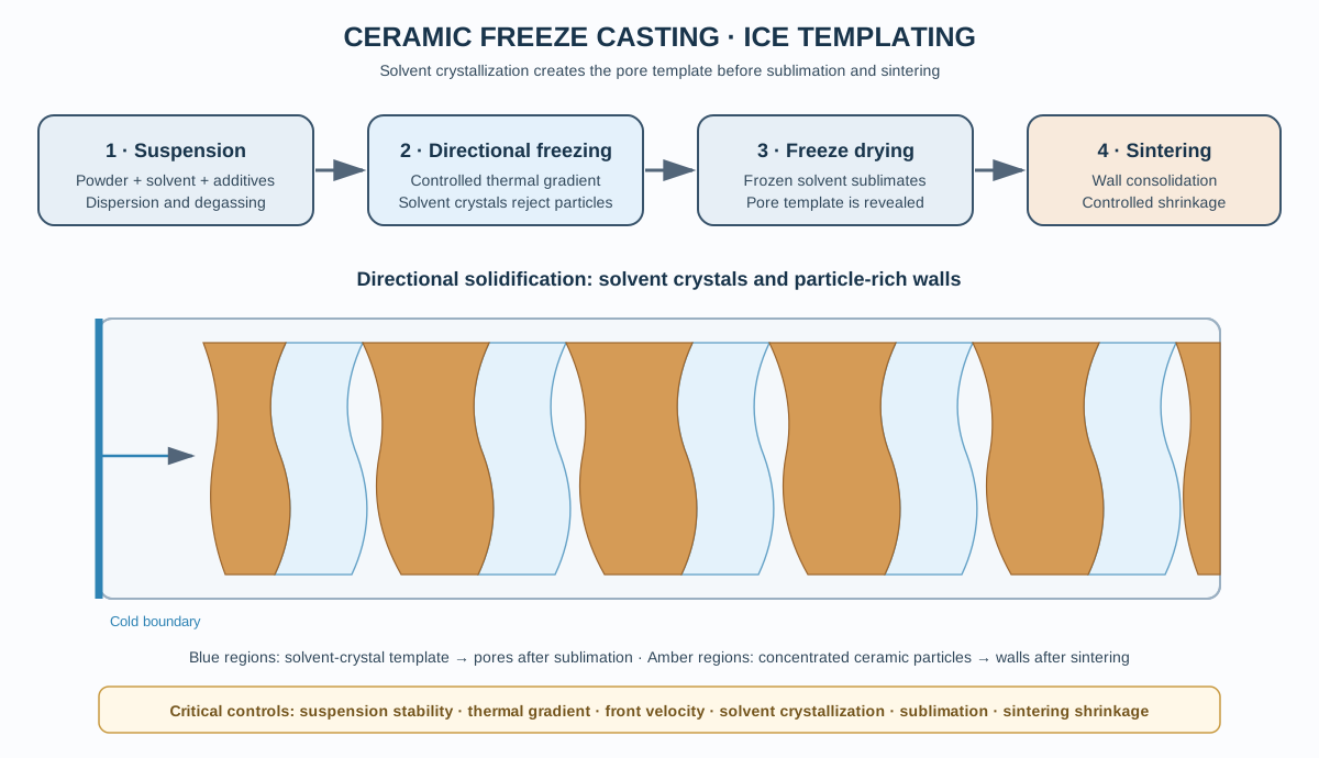
The process comprises four main operations:
- Prepare a stable ceramic suspension in a selected solvent or solvent mixture.
- Solidify the suspension under controlled thermal gradients and boundary conditions.
- Remove the frozen solvent, commonly by freeze-drying (sublimation).
- Consolidate the particle framework by an appropriate thermal treatment.
During solidification, the solvent-rich phase forms crystals while the ceramic particles are concentrated in the intercrystalline regions. After sublimation, the spaces formerly occupied by solvent crystals become pores, while the concentrated particle regions become ceramic walls or struts.
Freeze casting is the broader term because the templating solvent need not be water. Ice templating is commonly used for aqueous systems. The process is also described as directional freeze casting, frozen-solvent templating or freeze-drying-based templating, depending on the solvent and experimental configuration.
Freeze casting is not equivalent to conventional freeze drying of a pre-formed gel. In freeze casting, the freezing step deliberately creates the architecture by solvent-crystal growth and particle segregation. In ordinary freeze drying, the objective may instead be to preserve a structure that already exists before freezing.
3. The physics of directional solidification
The central event in freeze casting is the movement of a solidification front through a suspension. Solvent crystals grow while ceramic particles are either rejected into the liquid channels between crystals or engulfed by the advancing solid.
3.1 Particle rejection and engulfment
Whether a particle is pushed ahead of a growing crystal or captured within it depends on the balance of interfacial energies, particle size, front velocity, thermal conditions and the local hydrodynamic and colloidal environment.
When particles are rejected, they accumulate between neighbouring solvent crystals. Continued growth concentrates the particles into walls. If particles are engulfed, the resulting structure can contain particles inside the templating phase, disrupting the intended separation between pores and ceramic walls.
The transition between rejection and engulfment is not governed by a single universal critical velocity. It depends on the particle–solvent–crystal system and the local solidification conditions. Therefore, a reported front velocity should not be transferred directly between different powders or solvents without validation.
3.2 Thermal gradient and freezing-front velocity
Two important process variables are:
- Thermal gradient, (G): the temperature change per unit distance near the solidification front.
- Front velocity, (V): the speed at which the solidification front advances through the suspension.
The thermal gradient and front velocity influence crystal spacing, growth direction, interface stability and particle redistribution. In a controlled directional-freezing arrangement, heat is extracted preferentially through one boundary so that the solidification front advances along a defined direction.
The thermal gradient and front velocity should be measured or estimated for the actual mould geometry. The programmed cooling rate of a stage is not necessarily equal to the local front velocity inside the suspension.
3.3 Why pore spacing depends on freezing conditions
The spacing between solvent crystals determines the spacing between ceramic walls and, after sublimation, the characteristic pore dimensions. In many systems, faster directional solidification produces finer characteristic structures, while slower growth can produce coarser features. The exact relationship depends on solvent, solids loading, additives, thermal gradient and front stability.
Do not treat a single empirical spacing law as universal. Establish the relationship for the selected system by combining recorded thermal conditions with quantitative image analysis of the resulting structure.
4. Freezing configurations and architecture
4.1 Unidirectional freezing
Unidirectional freezing extracts heat mainly through one surface, producing a preferred growth direction. The resulting pore channels are commonly aligned approximately with the direction of solvent-crystal growth, while ceramic walls form between them.
This configuration is useful when directional transport or anisotropic mechanical behaviour is desired. The orientation of the thermal gradient must be considered relative to the intended component geometry and service loading.
4.2 Radial freezing
Radial or axisymmetric freezing can be produced by controlling heat extraction around a central or peripheral boundary. It can generate radially oriented channels and is relevant to tubular or cylindrical architectures.
The local direction of the thermal gradient changes with position, so the pore orientation is not uniform across the entire component. This must be considered when evaluating mechanical or transport properties.
4.3 Bidirectional and patterned freezing
Multiple cooled boundaries or patterned thermal contacts can create more complex pore arrangements. Such designs may produce intersecting, curved or spatially varying channels.
The resulting architecture depends on the competition between different solidification fronts. Small changes in boundary contact, mould thermal conductivity or cooling conditions can shift the location where fronts meet.
4.4 Solvent-dependent morphologies
The solvent’s crystal habit influences the morphology of the templated pores. Aqueous systems commonly produce lamellar or cellular structures depending on the conditions and additives. Other solvents can generate different crystal habits and pore shapes.
The pore architecture should be described quantitatively rather than labelled only as lamellar or dendritic. Useful descriptors include: - Mean pore width and its distribution. - Wall thickness and wall-spacing distribution. - Orientation distribution. - Channel continuity and connectivity. - Total and open porosity. - Anisotropy in three dimensions.
5. Additives and interfacial control
Additives can modify suspension stability, solvent crystallization, particle rejection, wall packing and green strength. Their effects are coupled: an additive that changes the solvent-crystal interface may also alter viscosity or particle dispersion.
Common additive functions include:
| Dispersant |
Stabilizes particles and reduces agglomeration |
May alter interfacial energy or remain as an organic residue |
| Binder |
Improves cohesion of the freeze-dried walls |
Can increase drying or debinding demands |
| Ice-structuring agent |
Modifies solvent-crystal growth and morphology |
May compete with particle rejection or change wall chemistry |
| Surfactant |
Changes wetting and interfacial behaviour |
Can cause foaming or destabilize the suspension |
| Rheology modifier |
Controls flow and suspension stability |
Excessive viscosity can disrupt front propagation |
Additive concentration should be optimized experimentally. A change in pore morphology should not be attributed to a single interfacial mechanism unless supported by appropriate evidence, because additives can influence several coupled phenomena.
6. Mould design and thermal boundary conditions
The mould is part of the thermal system. Its conductivity, thickness, contact resistance and geometry influence the temperature field and therefore the solidification front.
Important design considerations include: - Controlled contact between the mould and cooling surface. - Reproducible thermal resistance at the cold boundary. - Thermal insulation of surfaces that should not extract heat. - Mould material compatibility with the solvent and temperature range. - A geometry that avoids unintended nucleation at multiple surfaces. - Sufficient mechanical support during freezing and transfer.
A high-conductivity mould can improve heat transfer but may also promote unwanted lateral heat extraction. Insulation can help establish a directional gradient, but poor insulation or variable contact pressure can produce asymmetric structures.
Record the mould material, dimensions, cooling-surface contact, insulation arrangement and sensor positions. These details are necessary for reproducing the thermal boundary conditions.
7. Freezing equipment and process monitoring
A freeze-casting setup does not necessarily require a commercial freeze caster, but it must provide reproducible thermal conditions. A laboratory system may include a controlled cold stage, heat-transfer block, mould, insulation and temperature sensors.
Useful measurements include: - Temperature at the cold boundary. - Temperature at selected positions within or adjacent to the mould. - Cooling-stage temperature and programmed ramp. - Time for the front to traverse the sample. - Sample dimensions and mould contact conditions. - Ambient conditions where they influence heat leakage.
Thermocouples should be positioned so that they do not significantly disturb the local thermal field. For advanced studies, infrared imaging or in-situ X-ray methods can provide additional information, although each technique has its own spatial and temporal limitations.
The temperature history should be retained as a time series. A single final temperature does not describe the freezing process.
8. Freeze drying and solvent removal
After complete solidification, the frozen solvent is removed by sublimation under conditions that maintain the frozen phase while allowing vapour transport. The resulting dry body preserves the architecture formed during freezing, provided that the structure does not collapse or crack during the process.
8.1 Primary drying
During primary drying, the frozen solvent sublimes. Heat must reach the sublimation front while vapour is transported through the developing porous structure to the condenser.
The process is controlled by: - Shelf or cold-stage temperature. - Chamber pressure. - Heat-transfer resistance. - Vapour-transport resistance. - Sample thickness and geometry. - Solvent phase behaviour.
If heat input is excessive, local melting can occur and damage the pore architecture. If heat input is too low, drying time can become unnecessarily long.
8.2 Secondary drying
After the bulk frozen solvent has been removed, residual adsorbed or bound solvent may remain. Secondary drying removes this residual fraction by controlled heating under reduced pressure, subject to the thermal stability of the green body and its additives.
The distinction between primary and secondary drying should be reflected in the process record. A visually dry specimen does not necessarily prove that residual solvent has been removed.
8.3 Transfer and handling
The freeze-dried body can be fragile, particularly at low solids loading or when the walls are thin. Transfer should minimize vibration, bending and local contact loads. Support fixtures may be required for thin-walled or elongated parts.
Mass, dimensions and visible defects should be recorded before and after drying. These measurements help distinguish freezing-related defects from damage introduced during sublimation or handling.
9. Sintering and preservation of pore architecture
The freeze-dried body is a porous ceramic-particle framework. Sintering creates particle necks and strengthens the walls, but it also causes shrinkage and may reduce pore size or connectivity.
The final structure is therefore not identical to the frozen-solvent template. It is modified by: - Initial particle packing within the walls. - Green-body density. - Binder or additive removal. - Sintering temperature and dwell. - Grain growth and pore migration. - Differential shrinkage and wall coalescence.
The thermal schedule should be developed for the actual powder and target architecture. A schedule optimized for maximum density may destroy the open-channel structure that motivated freeze casting.
9.1 Linear shrinkage
For a measured direction:
[ S_L = % ]
where (L_g) is the dimension of the freeze-dried green body before sintering and (L_f) is the corresponding final dimension. State the reference condition clearly and measure more than one direction because freeze-cast bodies are often anisotropic.
9.2 Relative density and porosity
For a body with measured bulk density (b) and an appropriate theoretical density ({th}), a first estimate of total porosity is:
[ P - ]
This estimate assumes that the selected theoretical density represents the solid phase and that the bulk-density measurement captures the specimen’s external volume. It does not distinguish open from closed porosity and may be inaccurate for multiphase or compositionally non-uniform bodies.
Use complementary methods where needed: Archimedes measurements, gas pycnometry, mercury intrusion (with its limitations), gas adsorption for finer pores, and three-dimensional imaging for channel architecture.
10. Defect diagnosis
| Non-directional or intersecting channels |
Multiple nucleation sites or uncontrolled heat extraction |
Mould contact, insulation, thermal map |
| Dense region near a boundary |
Particle capture, local front instability or sedimentation |
Local microstructure, front history, suspension stability |
| Strong pore-size gradient |
Changing front velocity or thermal gradient |
Temperature time series, front position |
| Cracked green body |
Thermal stress, poor wall cohesion or handling damage |
Freezing history, binder level, green strength |
| Collapsed channels |
Melting during primary drying or insufficient wall strength |
Product temperature, chamber pressure, wall packing |
| Warpage |
Asymmetric freezing, drying or support conditions |
Directional dimensions, thermal boundary conditions |
| Excessive shrinkage |
Low wall packing, high organic content or aggressive sintering |
Green density, additive content, dilatometry |
| Blocked or closed channels |
Wall deformation, particle redistribution or excessive sintering |
3D imaging, open-porosity measurement |
A defect observed after sintering may originate much earlier. Preserve specimens after freezing, after freeze drying and after sintering when diagnosing a new process.
11. Characterization of pore architecture
A complete characterization strategy should combine two-dimensional and three-dimensional methods.
SEM is useful for examining wall morphology, particle packing and local pore shape. Fracture surfaces should be interpreted carefully because preparation can introduce artefacts.
X-ray computed tomography can quantify three-dimensional channel orientation, connectivity, wall thickness and defects when the spatial resolution is adequate for the relevant feature size.
Mercury intrusion porosimetry can provide information about accessible pore-throat sizes, but the result is influenced by pore-entry geometry and the applied pressure; fragile structures may be damaged.
Gas adsorption is useful for finer pores and surface area, but it does not characterize the large aligned channels that often define freeze-cast architecture.
Archimedes methods and pycnometry provide complementary density information. The method and assumptions should be reported, especially when the body contains open, closed and hierarchical porosity.
For anisotropic materials, characterize sections parallel and perpendicular to the freezing direction. A single two-dimensional micrograph cannot establish three-dimensional channel connectivity.
12. Process-development workflow
Stage A — Suspension - Characterize powder size, morphology and surface area. - Select solvent and compatible dispersant. - Measure rheology over the practical solids-loading range. - Verify stability over the complete preparation and casting interval.
Stage B — Freezing - Define the mould and thermal-boundary design. - Record temperature at multiple positions. - Measure or estimate front velocity. - Compare pore morphology across controlled freezing conditions.
Stage C — Freeze drying - Select primary-drying conditions from solvent phase behaviour. - Verify that the product remains frozen during sublimation. - Establish secondary-drying conditions where required. - Record mass and dimensional changes.
Stage D — Sintering - Develop a schedule that strengthens the walls while retaining the target channels. - Measure shrinkage in multiple directions. - Evaluate density, open porosity and wall microstructure.
Stage E — Architecture qualification - Quantify pore size, wall thickness and orientation distributions. - Assess connectivity using 3D imaging where possible. - Measure anisotropic mechanical or transport properties relevant to the intended application. - Report repeatability across specimens and batches.
13. Minimum reporting checklist
A reproducible freeze-casting study should report:
- Powder composition, particle-size distribution, morphology and specific surface area.
- Solvent identity, purity and relevant phase behaviour.
- Solids loading in vol%, with the density basis stated.
- Dispersant, binder and other additive identities and concentrations.
- Slurry mixing, deagglomeration, degassing and stability protocol.
- Rheological data and measurement conditions.
- Mould material, dimensions, insulation and cooling-boundary configuration.
- Temperature-sensor positions and complete temperature histories.
- Freezing-front direction and velocity, where measured or estimated.
- Freeze-drying pressure, product temperature, primary-drying and secondary-drying conditions.
- Sintering atmosphere, heating/cooling programme and dwell.
- Green and final dimensions, density, shrinkage and porosity.
- Quantitative pore and wall morphology, including orientation and connectivity.
- Replicate count, uncertainty and defect statistics.
14. Key conclusions
Freeze casting is a structure-forming process governed by solvent crystallization and particle redistribution. The pore network is not created simply by drying a porous slurry; it is templated during solidification. Suspension stability determines the starting conditions, interfacial and kinetic effects determine particle rejection, thermal boundary conditions determine the growth direction and scale, freeze drying removes the solvent template, and sintering determines how much of the designed architecture survives.
The most reliable development strategy is to measure the thermal history and quantify the resulting three-dimensional architecture. Reporting only a cooling rate and a representative SEM image is insufficient to reproduce a directional freeze-casting process.
References
- S. Deville, “Freeze-Casting of Porous Ceramics: A Review of Current Achievements and Issues,” Advanced Engineering Materials 10 (2008), 155–169. https://doi.org/10.1002/adem.200700270.
- “A review of fabrication strategies and applications of porous ceramics prepared by freeze-casting method,” Ceramics International 42 (2016), 2907–2925. https://doi.org/10.1016/j.ceramint.2015.10.148.
- G. Shao, D. A. H. Hanaor, X. Shen and A. Gurlo, “Freeze Casting: From Low-Dimensional Building Blocks to Aligned Porous Structures—A Review of Novel Materials, Methods, and Applications,” Advanced Materials (2020). https://doi.org/10.1002/adma.201907176.
- S. Deville, S. Meille and J. Seuba, “A meta-analysis of the mechanical properties of ice-templated ceramics and metals,” Science and Technology of Advanced Materials 16 (2015), 043501. https://doi.org/10.1088/1468-6996/16/4/043501.
- M. A. White et al., “Investigations of ice-structuring agents in ice-templated ceramics,” Journal of the American Ceramic Society 100 (2017), 5066–5074. https://doi.org/10.1111/jace.15060.
- L. N. R. M. Santos et al., “Freeze-casting applied to ceramic materials: a short review of the influence of processing parameters,” Cerâmica 67 (2021), 1–13. https://doi.org/10.1590/0366-69132021673812923.
- “Freeze casting,” Nature Reviews Methods Primers 4 (2024), Article 28. https://doi.org/10.1038/s43586-024-00307-5.
- E. Munch et al., “Architectural Control of Freeze-Cast Ceramics Through Additives and Templating,” Journal of the American Ceramic Society (2009). https://doi.org/10.1111/j.1551-2916.2009.03087.x.
- L. dos Santos Aguilera et al., “A homemade freezing unit for ice-templating,” Journal of Applied Research and Technology 20 (2022), 472–480. https://doi.org/10.22201/icat.24486736e.2022.20.4.1328.