Ceramic Extrusion: Paste Preparation, Rheology, Die Design and Defect Control
Ceramic Extrusion: Paste Preparation, Rheology, Die Design and Defect Control
Ceramic extrusion is a continuous forming process in which a plastic or viscoplastic ceramic body is forced through a shaped die to produce a continuous profile. It is particularly suited to components with a constant or slowly varying cross-section, including rods, tubes, channels and multi-channel structures.
The engineering challenge is to create a paste that is simultaneously formable, extrudable and shape-retaining. It must deform under the available pressure, flow through the barrel and die without excessive pressure or internal damage, and retain its geometry after leaving the die. Subsequent drying and thermal treatment must remove liquid and organics without unacceptable distortion or cracking.
This article focuses on conventional paste extrusion. Layer-by-layer extrusion-based additive manufacturing is related but has additional requirements for filament placement, interlayer bonding and shape retention; it is not equivalent to continuous profile extrusion.
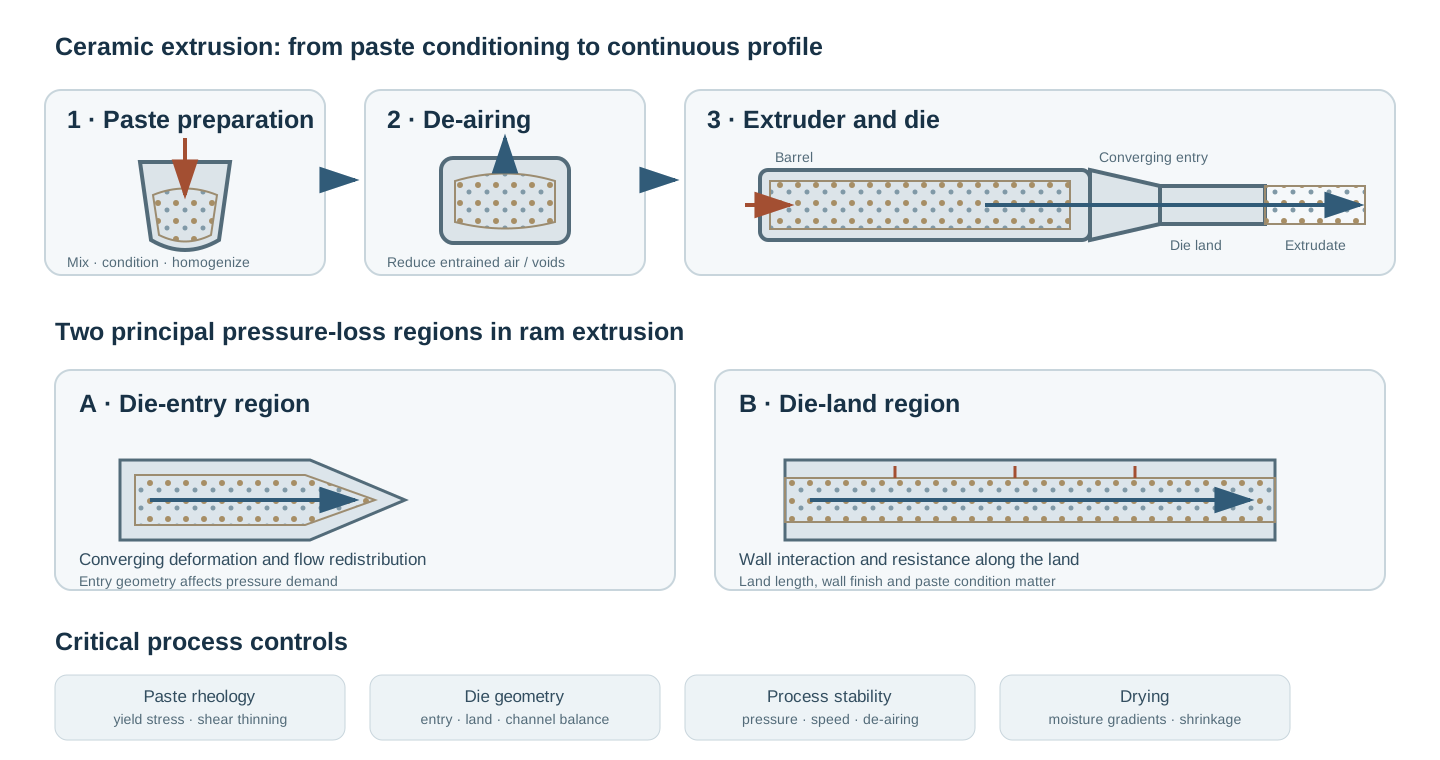
1. Process principle and equipment configurations
A prepared ceramic paste is fed into an extrusion unit. Pressure generated by a piston, ram or rotating screw drives the paste through a converging region and then through a die land. The die defines the cross-sectional geometry.
1.1 Ram or piston extrusion
A piston applies pressure to a batch of paste contained in a barrel. The paste moves through a die at the barrel outlet. Ram extrusion is useful for laboratory-scale rheological characterization and short production runs. It provides direct control of ram displacement or force, but batch charging and discontinuous operation may limit throughput.
1.2 Screw and auger extrusion
A rotating screw or auger conveys, compresses and pressurizes the paste continuously. It is suitable for industrial production and long profiles. Screw geometry, speed, feed consistency and wear influence pressure and output. Shear heating, residence time and feed nonuniformity require control.
1.3 Vacuum de-airing
Many ceramic extrusion lines include a vacuum chamber or de-airing stage. Entrained air can compress under pressure and expand downstream, contributing to laminations, voids or surface defects. De-airing reduces this risk but does not correct poor formulation, dry agglomerates or nonuniform feed. Vacuum level, residence time, paste permeability and feed rate must be compatible.
2. Paste formulation
Ceramic extrusion generally requires a concentrated particulate body containing a liquid phase and, where necessary, additives that control plasticity, cohesion and processing stability.
A formulation may contain ceramic powder, liquid vehicle, plasticizer, binder, dispersant or deflocculant, lubricating/extrusion-aid additive, and pore-forming additive where required. The purpose and interaction of each additive should be established experimentally. A formulation that flows easily may have inadequate green strength; a paste with excellent shape retention may require excessive extrusion pressure.
2.1 Solids loading
Solids loading strongly affects paste rheology, drying shrinkage and final pore structure. Increasing solids loading can reduce the amount of liquid to be removed, but may also increase yield stress and extrusion pressure or reduce process tolerance.
State whether solids loading is a mass fraction or volume fraction:
[ w_s= ]
[ _s= ]
where (s) and (l) denote solid and liquid phases. Mass and volume fractions are not interchangeable; conversion requires the relevant densities.
The optimum is not necessarily the maximum achievable solids loading. It is the loading that provides a stable operating window with acceptable pressure, extrudate integrity and drying behaviour.
2.2 Plasticity, cohesion and additive compatibility
Plasticity describes the ability of a paste to undergo permanent deformation without fracture under forming stress. Cohesion is needed to maintain a continuous extrudate after it leaves the die. Too little plasticity may cause high pressure, discontinuous flow or cracking. Excessive plasticity or insufficient structural recovery can cause sagging, spreading or collapse.
Additives can influence several process stages. An additive that improves die-wall lubrication may also alter green strength, drying, burnout or residual chemistry. Evaluate formulation decisions across the full process route, not only by extrusion force.
3. Mixing, ageing and feed conditioning
The purpose of mixing is to distribute solids, liquid and additives uniformly and remove persistent dry regions or agglomerates. A practical sequence may involve dry blending, staged liquid addition, kneading or intensive mixing, ageing and de-airing. The exact sequence depends on powder and additive chemistry.
Important controls include addition order and rate, mixing energy and duration, temperature rise, moisture distribution, batch size, ageing time and sealed storage. Ageing can allow moisture and additives to redistribute and change paste consistency. It should be controlled and reported rather than treated as an unspecified waiting period.
A useful feed-release protocol includes visual inspection, moisture or mass-loss checks, a consistency/rheology test and an extrusion trial under a defined geometry and speed.
4. Rheology of ceramic pastes
Ceramic extrusion pastes are commonly non-Newtonian and may show yield-stress, shear-thinning, thixotropic or viscoelastic behaviour. The response depends on solid fraction, particle interactions, liquid phase, additives, temperature and shear history.
4.1 Yield stress and idealized models
A simple Bingham model is:
[ =_y+_p (_y) ]
where ( au) is shear stress, ( au_y) is yield stress, (mu_p) is plastic viscosity and (dot{}) is shear rate. Below yield, the ideal model predicts no steady flow. Real ceramic pastes may deviate substantially; the model is a first description, not a universal constitutive equation.
A power-law model is:
[ =K^{n} ]
where (K) is the consistency index and (n) is the flow behaviour index. For shear-thinning behaviour, (n<1). A yield-stress term may be added in a Herschel–Bulkley model:
[ =_y+K^{n} ]
for stresses above the yield condition.
4.2 Thixotropy and structural recovery
Thixotropy is a time-dependent reduction in structure or apparent viscosity under sustained shear, followed by recovery during rest. It can influence restart after pauses, pressure drift during a long run, extrudate shape after die exit and batch-to-batch consistency. A single viscosity value cannot fully characterize a thixotropic paste. Use controlled pre-shear, rest time and measurement sequence when comparing batches.
5. Rheological and extrusion characterization
No single test fully predicts extrudability. A useful programme combines rotational rheometry, compression or penetration tests, moisture measurements and actual extrusion trials.
Rotational rheometry can provide flow curves, yield-stress estimates, oscillatory response and thixotropic recovery. Geometry selection and gap should account for particle size and wall-slip risk. Roughened or vane geometries may be useful for some concentrated pastes, but results remain geometry- and protocol-dependent.
A ram extruder measures force or pressure as a function of ram displacement or extrudate velocity. Tests using different die diameters and land lengths help separate deformation at the die entry from resistance along the die land.
Record barrel and die dimensions, die entry geometry, die-land length, paste temperature and conditioning history, ram velocity and displacement, force/pressure response, and extrudate dimensions and surface quality.
5.1 Benbow–Bridgwater model
For a cylindrical ram extruder with a circular die, a commonly used semi-empirical relationship separates pressure drop into entry and die-land contributions:
[ P=2(_0+V^m)() +4()(_0+V^n) ]
Here (P) is total extrusion pressure, (D_0) barrel diameter, (D) die diameter, (L) die-land length and (V) extrudate velocity. The parameters (sigma_0,α,m) describe the entry contribution; ( au_0,β,n) describe the die-land wall-flow contribution.
The first term represents deformation and convergence at the die entry; the second represents resistance along the die land. Parameter definitions and exponent conventions can differ between publications and model variants. The equation is semi-empirical and relies on assumptions about flow and wall interaction. It is most useful for comparing a defined paste and geometry range, not as a universal predictive law for arbitrary dies.
A robust fitting programme uses multiple die geometries and extrusion velocities. Do not fit all parameters from a single pressure measurement.
6. Die design and flow
The die converts pressurized paste into the required cross-section. Its geometry affects pressure demand, flow distribution, surface quality and residual stress.
6.1 Die entry and contraction
The entry region accelerates and redirects paste from the barrel into the smaller die opening. Abrupt contractions can create high deformation demand and nonuniform flow. A tapered or contoured entry may reduce abrupt changes, but the appropriate geometry depends on paste and profile.
6.2 Die land
The die land is the constant-cross-section portion that guides and stabilizes the extrudate. Increasing land length can improve dimensional guidance or surface quality in some systems, but it also increases wall resistance and extrusion pressure. An excessively short land may provide insufficient stabilization; an excessively long land can raise pressure and sensitivity to wall friction.
6.3 Die swell and dimensional recovery
The extrudate may expand or change dimensions after leaving the die due to elastic recovery, stress redistribution, liquid migration or structural relaxation. This response is often called die swell, although mechanisms in concentrated ceramic pastes differ from those in polymer melts. Measure dimensions at a defined distance and time after die exit. Do not assume the die opening equals the final wet-extrudate dimensions.
6.4 Multi-channel and complex dies
Multi-channel dies require balanced flow resistance across all channels. Unequal channel lengths, local restrictions, manifold geometry, wall finish or paste distribution can create different exit velocities and profile distortion. Consider flow-path length and area, entry transitions, manifold symmetry, wall finish, channel-to-channel pressure balance, cleaning access and blockage risk.
7. Extrusion operation and monitoring
A stable process requires consistent feed, controlled pressure and a steady extrudate take-off rate. Monitor feed rate, screw speed or ram velocity, extrusion pressure and fluctuations, paste temperature, vacuum level where used, extrudate speed and dimensions, surface condition, and die/screw wear.
A gradual pressure rise may indicate feed drying, temperature change, blockage or wear-related changes. Sudden fluctuations may indicate air pockets, feed interruption, agglomerates or unstable flow. Diagnose the cause before changing pressure or speed setpoints.
8. Extrudate handling and support
The freshly extruded body may have limited strength and can deform under its own weight or contact forces. Support, cutting and transfer should avoid bending, stretching, twisting or local compression. For long profiles, control take-off speed relative to extrusion speed, support spacing and alignment, cutting method and timing, contact pressure, vibration and delay before drying.
A mismatch between extrudate output and take-off speed can stretch or compress the profile and alter dimensions.
9. Drying and shrinkage
Liquid removal after extrusion causes shrinkage and can generate internal stress. If moisture gradients develop, different regions shrink at different rates. The resulting stresses may produce warping, surface checking or through-cracks.
Drying strategy depends on profile thickness, geometry, liquid system, pore structure and green strength. Controlled humidity, airflow, temperature and support conditions may be required. Develop the schedule from mass-loss and dimensional measurements, not solely elapsed time.
For a measured linear dimension (L), linear drying shrinkage is:
[ S_L=% ]
where (L_0) is the initial wet-extrudate dimension and (L_d) is the dimension after the defined drying endpoint. State the measurement direction and endpoint. Anisotropic shrinkage is possible, especially for profiles with directional flow or geometric constraints.
10. Common defects and diagnosis
| Defect | Possible mechanism | Diagnostic direction |
|---|---|---|
| Surface tearing / roughness | Paste too stiff, poor lubrication, die-wall interaction, agglomerates or unsuitable die finish | Review moisture, formulation, die surface and extrusion rate |
| Laminations | Entrained air, poorly joined paste layers, feed discontinuity or inadequate de-airing | Inspect fracture planes; review pugging, vacuum and feed continuity |
| Internal voids | Air entrapment, feed defects or liquid/gas migration | Section the body; review mixing, vacuum and pressure history |
| Spiral or helical marks | Screw/feed pulsation, nonuniform flow or die/tooling effects | Correlate defect pitch with screw rotation and inspect the die |
| Die blockage | Oversized agglomerates, dried paste, foreign particles or narrow passages | Inspect feed screening, cleaning and die geometry |
| Swelling / profile distortion | Elastic recovery, nonuniform flow or insufficient green strength | Measure exit dimensions over time; review rheology and die design |
| Cracking after die exit | Insufficient plasticity/cohesion or excessive deformation | Review paste conditioning, contraction and extrusion rate |
| Warping during drying | Moisture gradients, uneven support or differential shrinkage | Map moisture loss and dimensions; adjust drying uniformity |
| Surface checking | Rapid surface drying or local tensile stress | Review airflow, humidity, temperature and surface condition |
| Channel-to-channel variation | Unequal flow resistance or manifold imbalance | Measure individual channel output and inspect die passages |
These are possible mechanisms, not unique diagnoses. Use pressure records, paste tests, die inspection, cross-sections and controlled trials to identify root causes.
11. Process optimization strategy
A practical sequence is to stabilize powder and liquid conditioning; define mixing and ageing; measure moisture and rheology; characterize extrusion pressure over a controlled velocity range; compare die-entry geometry and land length; confirm de-airing and feed continuity; establish a stable pressure, speed and take-off window; measure wet-extrudate geometry and green strength; develop controlled drying; and validate debinding and sintering.
Use designed experiments when formulation, die geometry and operating parameters interact. Keep paste history fixed when comparing dies, and keep die configuration fixed when comparing paste formulations.
12. Conventional extrusion versus extrusion-based additive manufacturing
Conventional ceramic extrusion produces a continuous profile through a die, often at a relatively steady production rate. Extrusion-based additive manufacturing deposits material along a programmed path, usually through a nozzle, to build a component layer by layer.
Both require suitable paste rheology and continuous flow, but additive manufacturing adds constraints on filament placement, layer bonding, path planning, overhang support and shape retention between layers. Results and parameter windows should not be transferred directly between the two processes without validation.
13. Quality control and characterization
Feed and paste: powder size distribution and agglomerate condition; moisture and solids loading; additive identity/content; mixing and ageing history; rheological flow curve and recovery behaviour.
Extrusion: extruder type and configuration; barrel, die-entry and die-land dimensions; ram/screw speed and pressure; vacuum and de-airing procedure; output rate and dimensions; surface quality and defect frequency.
Green body and downstream processing: green density and strength where relevant; dimensional stability and die swell; drying shrinkage by direction; drying mass-loss curve and defect inspection; debinding and sintering response.
14. Safety and equipment care
Follow powder and additive safety data sheets, particularly for fine powders and organic processing aids. Use appropriate local exhaust ventilation, dust containment, housekeeping and personal protective equipment.
Extruders can generate high pressure and significant mechanical forces. Keep guards and interlocks functional, isolate equipment before clearing blockages or cleaning the screw and die, and never loosen a die or pressure head while the system is pressurized. Follow the manufacturer’s isolation and maintenance procedures. Hot surfaces and moving screws introduce additional hazards.
15. Minimum reporting checklist
A reproducible study should report powder identity and particle-size characteristics; solids loading and additive identities/content; mixing, ageing, storage and de-airing; paste temperature and moisture; extruder type; barrel, die entry, profile and die-land dimensions; ram velocity or screw speed, pressure and output rate; vacuum conditions; rheological test protocol and fitted model; extrudate dimensions and measurement timing; drying conditions and shrinkage; defect observations; and subsequent debinding/sintering conditions.
References
- F. Händle (Ed.), Extrusion in Ceramics, Springer, Berlin, Heidelberg (2007). https://doi.org/10.1007/978-3-540-27102-4
- J. J. Benbow, E. W. Oxley and J. Bridgwater, “The extrusion mechanics of pastes—the influence of paste formulation on extrusion parameters,” Chemical Engineering Science 42 (1987), 2151–2162. https://doi.org/10.1016/0009-2509(87)85036-4
- “Die entry pressure drops in paste extrusion,” Chemical Engineering Science 53 (1998), 3215–3225. https://doi.org/10.1016/S0009-2509(98)00105-5
- “Extrusion of ceramic pastes: An alternative approach to obtain the Benbow’s model parameters,” Ceramics International (2014). https://doi.org/10.1016/j.ceramint.2014.05.145
- “Rheological studies on cordierite honeycomb extrusion,” Journal of the European Ceramic Society (2002). https://www.sciencedirect.com/science/article/pii/S0955221902000456
- X. Ang, J. Y. Tey, W. H. Yeo and K. P. Y. Shak, “A review on metallic and ceramic material extrusion method: Materials, rheology, and printing parameters,” Journal of Manufacturing Processes 90 (2023), 28–42. https://doi.org/10.1016/j.jmapro.2023.01.077
- “Extrusion-Based 3D Printing of Ceramic Pastes: Mathematical Modeling and In Situ Shaping Retention Approach,” Materials 14 (2021), 1137. https://doi.org/10.3390/ma14051137
- “The effect of interlayer drying on the ceramic paste extrusion process,” Ceramics International 51 (2025), 10681–10690. https://doi.org/10.1016/j.ceramint.2024.12.499