Template-Assisted Sol-Gel Synthesis and Surfactant-Directed Self-Assembly
Template-Assisted Sol-Gel Synthesis and Surfactant-Directed Self-Assembly
Template-assisted synthesis uses a structure-directing phase to influence the architecture of a developing inorganic or hybrid solid. In sol-gel processing, the template may be an amphiphilic molecule that self-assembles with precursor species, a preformed solid that is replicated, or a colloidal particle that defines larger voids.
The template does not simply act as a removable filler. Its size, shape, surface chemistry, packing, interactions with the precursor and removal pathway all influence the final structure. The inorganic network must form and become sufficiently stable before the template is removed; otherwise, the intended pore architecture may shrink, distort or collapse.
This article explains the main templating mechanisms and the practical variables that determine whether a designed mesostructure survives processing.
1. What is a template?
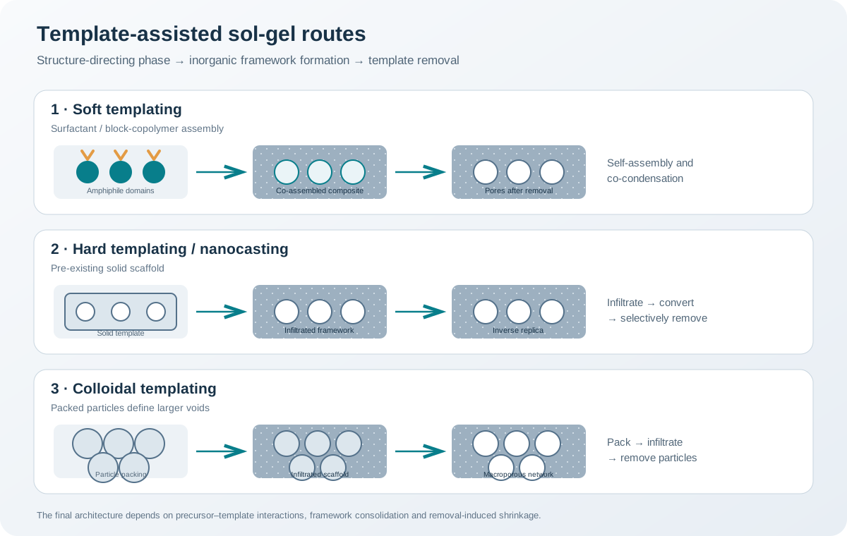
A template is a structure-directing entity that influences the shape, dimensions, arrangement or connectivity of the developing material. In sol-gel systems, three broad strategies are useful to distinguish:
- Soft templating: molecular or supramolecular species, commonly surfactants or block copolymers, self-assemble and organize inorganic precursor species around or alongside them.
- Hard templating: a pre-existing solid with a defined morphology or pore structure is infiltrated or coated by a precursor; removal of the solid leaves a negative replica or derived architecture.
- Colloidal templating: packed colloidal particles define voids between particles; subsequent infiltration and removal can generate an interconnected macroporous framework.
The categories describe different mechanisms, not a ranking from inferior to superior. Soft templates are often convenient for mesostructural organization, while hard and colloidal templates can provide stronger geometrical constraints. The best route depends on the desired length scale, framework chemistry, mechanical stability and acceptable process complexity.
2. Soft templating: surfactants and block copolymers
2.1 Amphiphilic molecules and self-assembly
A surfactant contains a hydrophilic head group and a hydrophobic tail. In a suitable solvent and concentration range, amphiphilic molecules can associate into micelles or other supramolecular arrangements. The geometry and stability of these assemblies depend on molecular structure, concentration, solvent, temperature, ionic strength and the presence of other species.
Block copolymers contain chemically distinct polymer blocks. Under appropriate conditions, they can form micelles or more extended ordered domains. Their larger molecular dimensions can be useful when a relatively large mesostructural length scale is required.
The assembly is dynamic. A micelle or polymer-rich domain can reorganize as solvent composition changes and as inorganic species condense. It should not be assumed that the structure observed in a dilute starting solution remains unchanged during gelation and drying.
2.2 How the inorganic network associates with the template
The central requirement is a compatible interaction between the template and the inorganic precursor or its hydrolysed/condensed species. Depending on the chemistry, interactions can include:
- Electrostatic attraction between oppositely charged head groups and precursor-derived species.
- Hydrogen bonding between polar groups.
- Coordination or ion-pairing interactions.
- Solvent-mediated association and hydrophobic effects.
- Cooperative assembly, in which template organization and inorganic condensation influence one another.
The classical notation often used to describe charge-assisted pathways includes S⁺I⁻, S⁻I⁺ and S⁰I⁰, where S denotes the surfactant head-group charge and I denotes the charge character of the inorganic species. These labels are simplified descriptions of interaction modes; they do not capture every counterion, solvent or hydrolysis equilibrium.
For nonionic block copolymers, hydrogen bonding and solvent-mediated interactions can be particularly important. The precursor must remain sufficiently mobile to reorganize while the inorganic framework develops enough connectivity to preserve the structure.
2.3 Cooperative assembly versus simple micelle replication
A common oversimplification is to imagine that preformed micelles are rigid moulds that are simply filled with inorganic material. In many sol-gel systems, the final mesostructure instead emerges through cooperative organization: precursor species and amphiphiles reorganize together as concentration, solvent composition and reaction progress change.
Consequently, the final pore dimensions are not necessarily equal to the dimensions of micelles measured in the initial solution. Framework shrinkage, wall formation, template packing and thermal conversion all affect the final dimensions.
3. Evaporation-induced self-assembly (EISA)
EISA is widely used to form ordered mesoporous films and can also be adapted to other geometries. In a typical process, a solution containing an inorganic precursor, an amphiphilic template and a volatile solvent is deposited as a film. Solvent evaporation increases the concentration of the nonvolatile components and changes the solvent environment.
A simplified sequence is:
- Prepare a compatible precursor–template solution.
- Deposit the solution by a coating or casting method.
- Evaporate solvent under controlled environmental conditions.
- Allow concentration and solvent-composition changes to drive organization of the organic and inorganic components.
- Develop the inorganic network through hydrolysis and condensation.
- Age or stabilize the composite structure as required.
- Remove the organic template using a suitable extraction or thermal route.
The ordering process is coupled to evaporation, chemical reactions and substrate interactions. It is therefore sensitive to:
- Relative humidity and airflow.
- Solvent volatility and solvent mixtures.
- Precursor-to-template ratio.
- Solution age and viscosity.
- Substrate surface energy and wetting.
- Withdrawal or coating speed.
- Film thickness and drying temperature.
- Rates of hydrolysis and condensation.
A faster evaporation rate is not automatically better. If solvent loss outruns structural reorganization or network formation, the film may develop cracks, gradients or poorly ordered domains. If evaporation is too slow or the solution is unstable, phase separation or macroscopic defects may occur. The useful process window must be established for the specific precursor–template–solvent combination.
4. Hard templating and nanocasting
Hard templating starts from a solid object whose shape or pore architecture is intended to be replicated. The precursor is introduced into or onto the template, converted into a stable framework, and the template is then removed.
A general workflow is:
- Select a template with the required geometry, pore dimensions and chemical resistance.
- Ensure that the precursor solution wets and accesses the relevant template surfaces or internal pores.
- Infiltrate the template, using repeated loading or controlled deposition when needed.
- Convert the precursor into a continuous framework.
- Remove the template by a chemically or thermally compatible method.
- Verify that the replica is continuous and that the intended architecture has survived.
The method is sometimes called nanocasting when a porous solid is used as a mould for a nanoscale replica. In an idealized case, the product is an inverse replica of the template, but real structures are affected by incomplete infiltration, precursor shrinkage, surface chemistry and template-removal damage.
4.1 Infiltration is a critical step
A precursor solution that does not wet the template or cannot enter its narrow channels will not produce a faithful replica. Relevant variables include:
- Contact angle and surface tension.
- Solvent compatibility with the template.
- Precursor size and solution viscosity.
- Pore-mouth restrictions and trapped gas.
- Hydrolysis or gelation occurring before infiltration is complete.
- Number of infiltration and conversion cycles.
Premature precipitation near the template entrance can block access to internal regions. Conversely, insufficient precursor loading can produce discontinuous walls or fragile replicas.
4.2 Template removal
Hard templates may require dissolution, etching, oxidation or another selective removal process. The removal chemistry must dissolve the template without attacking the product framework or changing its composition.
The choice is constrained by chemical compatibility, waste handling, process safety and the mechanical strength of the replica. A template-removal step should be assessed by mass balance and structural characterization rather than assumed complete from the visual appearance of the product.
5. Colloidal templating and macroporous structures
Colloidal templating uses a packed assembly of particles as a sacrificial scaffold. The spaces between particles are infiltrated by a precursor, which is converted into a continuous framework. Removal of the colloids leaves a network of larger voids.
The final pore dimensions depend on the colloid size distribution, packing order, infiltration quality, framework shrinkage and removal process. Monodisperse particles can support more regular packing, whereas polydispersity can alter packing density and pore connectivity.
A key distinction is that the resulting void network is related to the interstitial space between the template particles, not simply a direct copy of each particle’s outer diameter. Framework thickness and shrinkage further modify the final geometry.
6. Combining templates to create hierarchical porosity
Hard and soft templates can be combined to introduce more than one structural length scale. For example, a colloidal scaffold may define larger transport voids while a molecular template organizes smaller mesopores in the walls.
Hierarchical structures can offer a compromise between high internal surface area and shorter transport pathways. However, combining templates also introduces additional interactions and failure modes:
- The two templates may segregate rather than organize cooperatively.
- One template may block access to the other.
- Infiltration may be incomplete.
- Removal conditions suitable for one template may damage the other framework.
- Different shrinkage rates can create cracks or loss of connectivity.
The presence of two pore-size populations is not sufficient to establish a useful hierarchical network. Their connectivity and accessibility must be investigated.
7. Template removal: extraction, decomposition and calcination
The template must be removed or converted without destroying the inorganic architecture.
7.1 Solvent or chemical extraction
Extraction can be appropriate when the template is soluble in a compatible solvent or can be removed by controlled chemical treatment. It may reduce the thermal exposure of the inorganic framework and preserve surface hydroxyl groups or temperature-sensitive functionalities.
Potential limitations include incomplete extraction, repeated solvent use, residual surfactant and chemical attack on the framework. Verify the residue level using suitable methods such as thermogravimetric analysis, elemental analysis, infrared spectroscopy or other chemistry-specific measurements.
7.2 Thermal decomposition
Calcination can decompose or oxidize organic templates. It is operationally straightforward in many systems, but the temperature programme must account for the decomposition profile and the thermal stability of the inorganic framework.
Possible consequences include:
- Framework shrinkage and pore-size reduction.
- Loss of long-range mesoscopic order.
- Wall densification or crystallization.
- Grain growth and pore coarsening.
- Collapse of thin or weak framework walls.
- Changes in surface hydroxyl concentration or functional groups.
A TGA/DSC profile of the template-containing composite can help identify mass-loss and thermal-event intervals. It does not, by itself, prove complete template removal or preservation of the pore network. Combine thermal analysis with chemical and structural measurements.
7.3 Choosing a removal route
| Criterion | Extraction or chemical removal | Thermal removal |
|---|---|---|
| Thermal stability of framework | Useful when high temperatures are unsuitable | Requires framework to tolerate the chosen thermal programme |
| Organic residue | May require repeated extraction and verification | Can remove many organics, but incomplete oxidation or carbon residue may occur |
| Surface chemistry | May better preserve thermally sensitive groups | Can dehydroxylate or eliminate organic functionality |
| Framework shrinkage | Avoids some high-temperature shrinkage mechanisms | Thermal densification may shrink the pore structure |
| Process considerations | Solvent recovery, chemical compatibility and waste | Furnace atmosphere, exhaust treatment and thermal safety |
Neither route is universally preferable. Select the removal strategy based on framework chemistry, template identity, intended surface functionality and required structural fidelity.
8. Characterization: proving that templating worked
A successful templating process requires evidence for both composition and architecture.
| Question | Useful methods | What the measurement can establish |
|---|---|---|
| Is the template removed? | TGA, FTIR, elemental analysis, XPS where appropriate | Residual organic species or changes in surface chemistry |
| Is mesoscopic order present? | Small-angle X-ray scattering or small-angle XRD | Periodic or characteristic mesostructural length scales |
| What is the accessible surface area? | Gas physisorption and BET analysis | Probe-accessible specific surface area under stated conditions |
| What is the pore-size distribution? | Physisorption with a stated BJH or DFT-based model | Model-dependent distribution of accessible pores |
| What is the local morphology? | SEM and TEM | Framework walls, voids, defects and local ordering |
| Is the framework crystalline? | Wide-angle XRD or electron diffraction | Long-range crystalline phases and local order |
| Did the structure shrink? | Compare dimensions or lattice parameters before and after removal | Changes in characteristic structural length scales |
Small-angle scattering and wide-angle diffraction answer different questions. A low-angle reflection can indicate periodic mesoscopic organization; it does not identify the atomic crystal structure of the framework. Conversely, wide-angle diffraction can establish crystallinity without proving that the mesopores are ordered.
For thin films, grazing-incidence small-angle X-ray scattering (GISAXS) can be useful where available. Electron microscopy provides local evidence but should not be treated as a statistically complete description of the whole sample.
9. Common failure modes and diagnostics
| Observation | Possible cause | Diagnostic or corrective direction |
|---|---|---|
| No clear mesoscopic order | Weak template–precursor interaction, unsuitable solvent or insufficient organization time | Reassess compatibility, solution stability and evaporation conditions |
| Large domains or phase separation | Incompatible components or overly rapid concentration change | Examine solvent composition, humidity and solution age |
| Cracked films | Drying stress, excessive thickness or weak network formation | Adjust deposition and drying conditions; assess film thickness and gelation |
| Pores collapse after template removal | Framework not sufficiently condensed or removal too aggressive | Strengthen the framework before removal and compare extraction/thermal pathways |
| Residual organic material | Incomplete extraction or insufficient decomposition | Verify with TGA, FTIR or elemental analysis; revise removal conditions |
| Low accessible surface area | Pore blockage, collapse, incomplete template removal or inaccessible network | Combine physisorption with microscopy and chemical analysis |
| Poor hard-template replication | Incomplete wetting, trapped gas or premature gelation | Improve infiltration and separate loading from conversion where possible |
| Batch-to-batch variation | Changes in humidity, solvent loss, solution age or coating history | Record and control environmental and deposition parameters |
10. Experimental planning framework
A controlled development study can be organized into four stages.
Stage A — Template and precursor compatibility - Establish precursor stability in the selected solvent. - Check template solubility or dispersion. - Identify likely electrostatic, hydrogen-bonding or coordination interactions. - Check whether hydrolysis or condensation occurs too early.
Stage B — Assembly and network formation - Control solution age, concentration and deposition history. - Monitor viscosity or other suitable indicators of solution evolution. - Examine the as-formed composite before template removal. - For films, record humidity, temperature, coating speed and thickness.
Stage C — Template removal - Use thermal analysis to understand the composite’s decomposition behaviour. - Compare extraction and thermal routes only where chemically compatible. - Avoid transferring a removal temperature from another composition without validation. - Verify residual template and framework integrity.
Stage D — Structural verification - Use small-angle scattering or diffraction for mesoscopic order. - Use gas physisorption for accessible surface and pore analysis. - Use microscopy for local morphology. - Use wide-angle XRD and chemical analysis to assess the framework itself.
11. Reporting checklist
A reproducible templated sol-gel study should report:
- Template identity, grade, molecular characteristics and supplier where relevant.
- Precursor identity, solvent composition and solution preparation sequence.
- Precursor-to-template ratio and concentration basis.
- pH, catalyst, ionic strength and water content where relevant.
- Solution ageing time and temperature.
- Deposition method, substrate and environmental conditions for films.
- Drying and stabilization conditions.
- Template-removal chemistry, atmosphere, heating rate and dwell.
- Evidence for template removal and framework integrity.
- Mesostructural, surface-area and pore-size characterization methods.
- Replicate variability and limitations of the structural interpretation.
References
- N. D. Petkovich and A. Stein, “Controlling macro- and mesostructures with hierarchical porosity through combined hard and soft templating,” Chemical Society Reviews 42 (2013), 3721–3739. https://doi.org/10.1039/C2CS35308C.
- N. Pal and A. Bhaumik, “Soft templating strategies for the synthesis of mesoporous materials: inorganic, organic-inorganic hybrid and purely organic solids,” Advances in Colloid and Interface Science 189–190 (2013), 21–41. https://doi.org/10.1016/j.cis.2012.12.002.
- T. Kimura, “Evaporation-induced Self-assembly Process Controlled for Obtaining Highly Ordered Mesoporous Materials with Demanded Morphologies,” The Chemical Record 16 (2016), 445–457. https://doi.org/10.1002/tcr.201500262.
- H. Ghaedi and M. Zhao, “Review on Template Removal Techniques for Synthesis of Mesoporous Silica Materials,” Energy & Fuels 36 (2022), 2424–2446. https://doi.org/10.1021/acs.energyfuels.1c04435.
- P. Innocenzi, “Mesoporous ordered films via self-assembly: trends and perspectives,” Chemical Science 13 (2022), 13264–13279. https://doi.org/10.1039/D2SC04828K.
- K.-W. Kim and H. C. Moon, “Unconventional soft-templating strategies for mesoporous metal oxides: beyond evaporation-induced self-assembly and calcination-based conversion,” Polymer Journal 58 (2026), 1015–1026. https://doi.org/10.1038/s41428-026-01183-4.
Scope note: Template identity, precursor chemistry and removal conditions are strongly coupled. The pore architecture must be verified after template removal and after any subsequent thermal treatment; the initial template geometry alone does not establish the final pore structure.