Spray Coating and Aerosol-Assisted Sol-Gel Deposition
Spray Coating and Aerosol-Assisted Sol-Gel Deposition
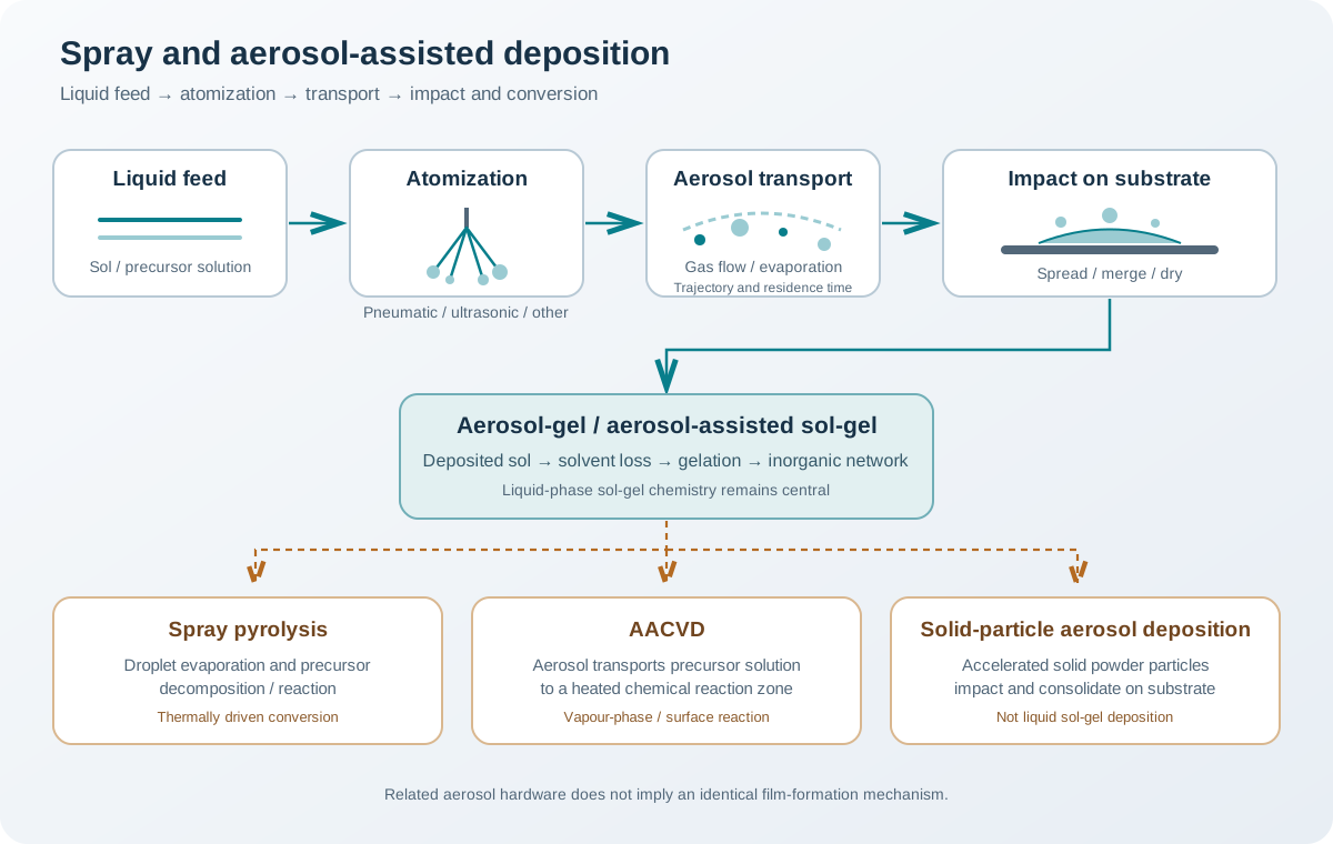
Spray-based deposition is a family of processes in which a liquid precursor is atomized into droplets, transported toward a substrate and converted into a coating or film. It can extend solution processing to larger areas and geometries that are difficult to coat by immersion or rotation. However, the word spray does not identify one unique mechanism. The droplet-generation method, droplet size distribution, carrier-gas flow, solvent evaporation and substrate temperature determine whether droplets merge into a wet film, gel after impact, or undergo substantial chemical conversion before reaching the surface.
This article focuses on liquid-precursor routes related to sol-gel chemistry. It distinguishes aerosol-gel deposition from spray pyrolysis and aerosol-assisted chemical vapour deposition (AACVD), which are related in their use of aerosols but differ in the location and mechanism of film formation.
1. The basic process chain
A generic spray-deposition system contains five coupled stages:
- Liquid feed preparation: a solution or sol with controlled composition, viscosity, surface tension and stability.
- Atomization: conversion of the liquid into droplets by a nozzle, ultrasonic transducer, pneumatic shear or another atomizer.
- Aerosol transport: movement of droplets through a carrier gas toward the substrate.
- Impact and conversion: droplet spreading, coalescence, evaporation, gelation or thermal reaction.
- Post-treatment: drying, removal of residual organics, densification or crystallization, as required.
The stages are coupled. For example, smaller droplets have a higher surface-area-to-volume ratio and usually exchange heat and mass more rapidly than larger droplets. But a smaller droplet is also more easily deflected by the gas flow and may evaporate before reaching the substrate. Therefore, atomizer settings cannot be optimized independently of the spray distance, gas flow, solvent volatility and substrate temperature.
2. Atomization methods
Atomization controls the initial droplet-size distribution, spray flux, spatial pattern and stability of the aerosol.
2.1 Pneumatic or air-assisted atomization
A liquid stream is disrupted by a high-velocity gas stream. The relative gas–liquid motion produces shear and aerodynamic instability, breaking the liquid into droplets.
Advantages - Simple and widely available hardware. - Adjustable liquid and gas flow rates. - Suitable for many coating solutions and suspensions.
Limitations - Droplet size distribution can be broad. - High gas flow may cause overspray, rebound or rapid solvent loss. - Nozzle geometry and operating conditions strongly affect the spray pattern. - Small passages may be vulnerable to clogging when the feed contains aggregates or particles.
Record the nozzle type, liquid feed rate, atomizing-gas pressure or flow, nozzle-to-substrate distance and spray angle. Pressure alone is not a sufficient description of the atomization condition.
2.2 Ultrasonic atomization
An ultrasonic transducer introduces high-frequency mechanical oscillations at a liquid surface or through a vibrating element. The resulting surface waves destabilize the liquid and generate droplets. The droplet distribution depends on the transducer frequency, liquid properties, liquid supply and atomizer design.
Ultrasonic atomizers can provide relatively controlled, low-velocity aerosols and may reduce the need for high-pressure atomizing gas. They are useful when a stable aerosol flux and relatively gentle transport are desirable.
However, ultrasonic atomization does not guarantee a narrow droplet distribution or uniform deposition. Feed composition, temperature, liquid level, transducer condition and aerosol transport still require control. The atomizer’s nominal frequency should not be treated as a complete specification of the generated droplet distribution.
2.3 Other atomization routes
Electrospray uses an electric field to deform a liquid meniscus and produce charged droplets or, under suitable conditions, much smaller charged species. Rotary and centrifugal atomizers use rotational motion to disperse liquid. These methods can be useful in specialized systems, but they introduce additional variables such as voltage, electrical conductivity, rotational speed and emitter geometry.
The appropriate atomizer depends on feed properties, target area, required droplet distribution, throughput and the thermal sensitivity of the precursor.
3. Droplet transport and evaporation
After atomization, droplets travel through a gas phase. Their trajectories depend on initial velocity, aerodynamic drag, gravity, gas flow, droplet diameter and the distance to the substrate.
A useful first distinction is between:
- Droplets that reach the substrate while still liquid. They impact, spread and may coalesce with neighbouring droplets.
- Droplets that partially evaporate in flight. Their solute concentration rises and their impact behaviour changes.
- Droplets that dry substantially before impact. They may arrive as concentrated residues or particles rather than as liquid droplets.
These pathways can coexist in one spray because the atomizer produces a distribution of droplet sizes and velocities.
3.1 Qualitative evaporation scaling
For an isolated liquid droplet evaporating under simplified conditions, a classical approximation is the D-squared law:
[ d2(t)=d_02-Kt ]
where (d_0) is the initial droplet diameter, (d(t)) is its diameter at time (t), and (K) is an effective evaporation constant. The value of (K) depends on solvent properties, gas temperature, vapour concentration, gas flow and heat and mass transfer.
This relation is a useful conceptual model, not a universal spray-deposition predictor. Real sprays contain interacting droplets, changing gas conditions, multicomponent solvents and non-volatile solutes. A sol droplet may also change viscosity, form a surface-rich shell or undergo gelation as solvent is lost.
3.2 Why spray distance matters
Increasing the distance between the atomizer and substrate generally increases the available transport and evaporation time. Depending on the process, this can:
- promote partial solvent removal before impact;
- reduce the liquid fraction reaching the substrate;
- alter droplet velocity and the impact footprint;
- increase sensitivity to carrier-gas flow and ambient conditions;
- reduce deposition efficiency if droplets are carried away or deposited on chamber walls.
The effect is not necessarily monotonic. A longer distance may improve some aspects of drying while reducing coating continuity or material utilization. Determine the useful range experimentally for the actual feed and equipment.
4. Droplet impact, spreading and film build-up
When a liquid droplet reaches a substrate, its behaviour depends on impact velocity, droplet size, viscosity, surface tension, substrate temperature, surface energy and roughness.
A droplet may: - spread and remain attached; - rebound or splash; - pin at its contact line; - evaporate before neighbouring droplets arrive; - merge with adjacent droplets to form a continuous liquid layer.
A key practical question is whether the spray produces a continuous wet film or a collection of partially overlapping droplet footprints. If droplets dry independently, the final surface can contain islands, ring-like deposits, gaps or a rough particulate texture. If they coalesce before solidification, a more continuous film may form, but excessive liquid accumulation can create runs, local thickness variations or drying cracks.
4.1 Dimensionless groups for interpreting impact
Dimensionless numbers help organize the competing effects. They do not replace measurement or provide a universal process recipe.
The Reynolds number compares inertial and viscous effects:
[ Re= ]
The Weber number compares inertia and surface tension:
[ We= ]
The Ohnesorge number compares viscous effects with inertia and surface tension:
[ Oh= ]
Here, () is liquid density, (U) is a characteristic impact velocity, (d) is droplet diameter, () is dynamic viscosity and () is surface tension.
Higher inertia relative to surface tension can promote stronger deformation and, under some conditions, splashing. Greater viscosity tends to resist rapid deformation. Actual outcomes also depend on contact angle, surface roughness, substrate temperature and whether the surface is already wet.
5. Aerosol-gel deposition: retaining sol-gel chemistry
In aerosol-gel or aerosol-assisted sol-gel deposition, a sol or reactive precursor solution is atomized and delivered to a substrate. The deposited liquid then undergoes sol-gel reactions, solvent evaporation and network formation. The key feature is that the sol-gel conversion remains central to film formation; the aerosol is the delivery route.
The exact sequence depends on the chemistry and substrate conditions. In one arrangement, droplets impact and merge before drying and gelation. In another, droplets lose a significant amount of solvent during flight and arrive as concentrated liquid or partially gelled deposits.
Potential benefits include: - deposition over areas that are difficult to immerse or rotate; - control of coating build-up through spray passes and feed delivery; - compatibility with solution-based precursor chemistries; - the possibility of coating selected regions using masks or controlled nozzle motion.
Challenges include: - droplet-size and spray-flux non-uniformity; - overspray and material loss; - local drying differences across the substrate; - nozzle contamination or blockage; - defects caused by incomplete coalescence or excessive liquid loading.
Aerosol-gel deposition should not be assumed to produce a film with the same structure as dip-coated or spin-coated material from the same sol. The droplet history and local drying pathway are different.
7. Process variables and their roles
| Variable | Main physical or chemical influence | What to monitor |
|---|---|---|
| Droplet-size distribution | Flight time, evaporation rate, impact footprint and surface texture | Size distribution, not only mean diameter |
| Liquid feed rate | Spray loading and local wetness | Stable feed rate and delivered mass |
| Atomizing-gas flow or pressure | Droplet breakup, velocity and plume shape | Flow/pressure and spray pattern |
| Ultrasonic frequency and power | Aerosol generation and droplet population | Atomizer settings and output stability |
| Nozzle-to-substrate distance | Transport time, evaporation and plume expansion | Distance and alignment |
| Spray angle | Footprint, shadowing and local deposition flux | Angle and nozzle orientation |
| Substrate temperature | Solvent evaporation, wetting and reaction rate | Actual surface temperature and uniformity |
| Carrier-gas flow | Droplet trajectory, residence time and heat/mass transfer | Flow, direction and chamber geometry |
| Sol viscosity and surface tension | Atomization, droplet deformation and spreading | Measured properties at deposition temperature |
| Sol concentration and ageing | Non-volatile loading, aggregation and gelation behaviour | Preparation history, age and stability |
| Pass overlap and scan speed | Spatial coating build-up | Programmed path and overlap |
| Ambient humidity | Solvent evaporation and moisture-sensitive chemistry | Relative humidity and temperature |
Do not assume that a single variable has one universal direction of influence. For example, raising substrate temperature may improve solvent removal but can also cause droplets to dry before they merge, producing a discontinuous or rough deposit. The useful temperature range depends on droplet arrival rate, solvent volatility and the chemistry of the precursor.
8. Defect diagnosis
| Observed feature | Possible mechanism | Checks and corrective direction |
|---|---|---|
| Isolated circular deposits or islands | Droplets dry before coalescing | Examine droplet size, arrival rate, substrate temperature and pass overlap |
| Ring-like deposits | Contact-line pinning and outward liquid flow during evaporation | Compare solvent volatility, wetting and drying conditions |
| Bare areas | Insufficient spray coverage, poor wetting or shadowing | Map the spray footprint and inspect substrate surface condition |
| Rough or powdery surface | In-flight drying, rapid impact drying or particle formation | Check spray distance, gas temperature and substrate temperature |
| Mud cracks | Thick wet build-up and constrained drying shrinkage | Reduce per-pass loading, use staged deposition or adjust drying |
| Runs and local thick regions | Excessive local liquid loading or poor drainage | Reduce feed per pass or improve scan and overlap control |
| Pinholes and bubbles | Trapped gas, contamination or rapid solvent evolution | Inspect feed filtration, substrate cleaning and drying sequence |
| Weak adhesion | Poor wetting, surface contamination or thermal stress | Reassess substrate preparation and post-treatment |
| Nozzle blockage | Aggregation, gelation or solvent loss at the nozzle | Check sol age, stability, filtration compatibility and nozzle cleaning |
| Batch-to-batch variation | Changes in sol age, atomizer output or ambient conditions | Record feed properties, atomizer condition and environmental data |
A defect should be diagnosed from its spatial pattern and its response to controlled changes. For example, a radial or plume-shaped variation points toward spray distribution, whereas cracks that appear only after thermal treatment suggest shrinkage or thermal stress.
9. Designing a controlled spray experiment
A useful development sequence is:
- Define the target: required coverage, substrate shape, final thickness, roughness, porosity and functional properties.
- Qualify the feed: verify composition, viscosity, surface tension where possible, stability, age and absence of uncontrolled aggregates.
- Characterize atomization: measure or obtain the droplet-size distribution and map the spray footprint.
- Establish transport conditions: fix nozzle distance, angle, carrier-gas flow and substrate position.
- Control the thermal environment: measure substrate temperature and record ambient conditions.
- Run a limited screening matrix: vary a small number of influential parameters while keeping the remaining conditions fixed.
- Measure deposited mass and coverage: use a reproducible method to compare material delivery and spatial uniformity.
- Characterize the dried layer: inspect continuity, thickness distribution, morphology and adhesion.
- Apply and evaluate post-treatment: determine whether drying, organic removal, densification or crystallization is required.
- Repeat independent runs: quantify reproducibility and distinguish systematic trends from spray-to-spray variation.
For a first process map, it is usually more informative to measure droplet distribution, spray footprint and deposited thickness than to optimize the final thermal treatment immediately. This separates delivery problems from conversion problems.
10. Characterization strategy
- Droplet sizing: laser diffraction, phase-Doppler methods or high-speed imaging, selected according to the expected size range and spray density.
- Spray visualization: high-speed imaging can reveal plume stability, droplet impact, splash and coalescence.
- Thickness and uniformity: profilometry, ellipsometry, cross-sectional microscopy or a suitable non-contact mapping method.
- Surface morphology: optical microscopy, SEM and AFM.
- Phase and crystallinity: XRD using a geometry appropriate for thin films.
- Chemical conversion: FTIR, Raman, XPS or thermal analysis of representative deposits, as appropriate.
- Adhesion: application-appropriate scratch, tape or pull-off testing.
- Functional performance: measure the property relevant to the intended coating application rather than relying on morphology alone.
The measurement method should match the length scale and film structure. A single cross-section is not a complete thickness-uniformity assessment, and a droplet-size mean does not describe the tails of a broad distribution.
11. Scale-up considerations
Spray coating is often considered for large-area processing, but scaling up requires more than increasing the liquid feed rate. The coating depends on the spatial distribution of droplets and on how the plume interacts with the substrate and surrounding gas.
Important scale-up questions include: - Is the spray flux uniform over the full target width? - Does the droplet-size distribution remain stable as throughput changes? - Can nozzle motion or multiple nozzles provide controlled overlap? - Does the substrate maintain a uniform temperature? - Are solvent vapours and overspray safely extracted? - Can the feed remain stable over the required production time? - Can nozzle wear, blockage and cleaning be monitored? - Is deposited-material utilization acceptable?
For continuous processing, line speed, nozzle arrangement, spray overlap, drying-zone length and thermal-zone residence time become coupled design variables. A laboratory condition should not be transferred directly to a production line without a transport and heat/mass-transfer assessment.
12. Minimum reporting checklist
A technically useful report should state:
- Precursor-solution or sol composition and preparation history.
- Sol age, viscosity, surface tension and temperature where measured.
- Atomizer type, model and operating settings.
- Droplet-size distribution and measurement method, if available.
- Liquid feed rate and carrier-gas identity and flow.
- Nozzle geometry, spray angle and nozzle-to-substrate distance.
- Substrate material, dimensions, surface preparation and temperature.
- Spray duration, scan speed, pass count and overlap.
- Ambient temperature and humidity.
- Drying and thermal-conversion conditions.
- Thickness mapping method, coverage, morphology and adhesion.
- Independent replicate count and batch-to-batch variation.
References
- M. Langlet, C. Vautey and N. Mazeas, “Some aspects of the aerosol–gel process,” Thin Solid Films 299 (1997), 25–32. https://doi.org/10.1016/S0040-6090(96)09405-9.
- “Production, Characterization, and Utilization of Aerosol-Deposited Sol−Gel-Derived Films,” Chemistry of Materials (1998). https://doi.org/10.1021/cm970612r.
- X. Hou and K.-L. Choy, “Processing and Applications of Aerosol-Assisted Chemical Vapor Deposition,” Chemical Vapor Deposition 12 (2006), 583–596. https://doi.org/10.1002/cvde.200600033.
- P. Marchand, I. A. Hassan, I. P. Parkin and C. J. Carmalt, “Aerosol-assisted delivery of precursors for chemical vapour deposition: expanding the scope of CVD for materials fabrication,” Dalton Transactions 42 (2013), 9406–9422. https://doi.org/10.1039/C3DT50607J.
- M. A. Butt, “Thin-Film Coating Methods: A Successful Marriage of High-Quality and Cost-Effectiveness—A Brief Exploration,” Coatings 12 (2022), 1115. https://doi.org/10.3390/coatings12081115.
- “A comprehensive review on the spray pyrolysis technique: Historical context, operational factors, classifications, and product applications,” Journal of Analytical and Applied Pyrolysis (2023). ScienceDirect article record.
- “A comprehensive review on ultrasonic spray pyrolysis technique: Mechanism, main parameters and applications in condensed matter,” Journal of Analytical and Applied Pyrolysis (2020). ScienceDirect article record.
- “Understanding Spray Coating Process: Visual Observation of Impingement of Multiple Droplets on a Substrate,” Journal of Shanghai Jiao Tong University (Science) (2018). https://doi.org/10.1007/s12204-018-1914-0.
Terminology note: Aerosol-gel deposition, spray pyrolysis, AACVD and solid-particle aerosol deposition are distinct process routes. They may share atomizers or transport hardware, but their film-formation mechanisms are not interchangeable. Always identify where solvent removal and chemical conversion occur when describing a spray-based synthesis method.