Sol-Gel Coatings and Thin-Film Deposition
Sol-Gel Coatings and Thin-Film Deposition
Sol-gel processing can convert a reactive solution or stable sol into a thin inorganic or hybrid layer on a substrate. The deposited liquid film undergoes drainage, solvent evaporation, gelation and often a subsequent thermal treatment. Each stage affects the final thickness, uniformity, porosity, adhesion and microstructure.
The most common laboratory coating routes include dip coating and spin coating. They share the same broad sol-gel chemistry but have different fluid-flow mechanisms and process controls. A coating recipe cannot be transferred between them simply by matching solution concentration or nominal deposition speed.
1. From a sol to a solid coating
A typical sol-gel coating sequence contains the following stages:
- Substrate preparation: remove contaminants and establish reproducible wetting.
- Solution preparation: prepare a stable sol with controlled viscosity, ageing history and particulate content.
- Deposition: bring the liquid into contact with the substrate using dip, spin or another coating method.
- Liquid-film evolution: allow drainage, centrifugal thinning or meniscus-controlled deposition, depending on the method.
- Drying and gelation: remove solvent and convert the deposited layer into a mechanically coherent network.
- Thermal conversion: remove residual organics, densify or crystallize the layer when required.
- Characterization: measure thickness, uniformity, adhesion, phase, roughness and functional properties.
The as-deposited wet thickness is not the final film thickness. Solvent loss, organic decomposition, densification and thermal shrinkage can substantially change the layer.
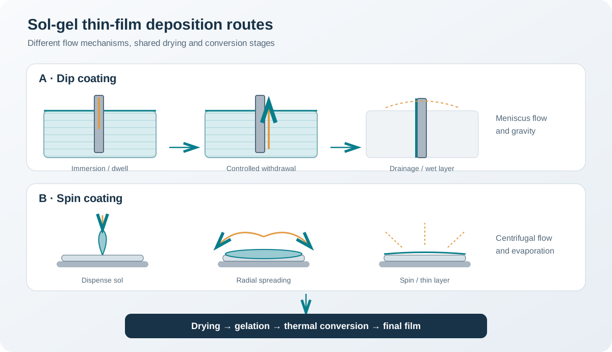
2. Dip coating
In dip coating, a substrate is immersed in a coating bath and withdrawn at a controlled speed. A liquid layer is entrained on the surface. Drainage and evaporation then determine how much material remains and how the layer consolidates.
A conventional cycle can be divided into immersion, dwell, withdrawal, drainage and drying. These stages should be controlled separately:
- Immersion: avoid trapping air and ensure the whole intended area is wetted.
- Dwell: allow the substrate to equilibrate with the solution; the required time depends on wetting and geometry.
- Withdrawal: control speed, acceleration and direction.
- Drainage: maintain a stable environment and avoid vibration or uncontrolled flow.
- Drying: control temperature, humidity and airflow to limit gradients and cracking.
2.1 Landau–Levich–Derjaguin relation
For a vertical plate withdrawn steadily from a Newtonian liquid in the low-capillary-number entrainment regime, the Landau–Levich–Derjaguin relation estimates the wet film thickness:
[ h_{wet}=0.94, ]
where:
- (h_{wet}) is the entrained wet-film thickness (m),
- () is dynamic viscosity (Pa·s),
- (U) is withdrawal speed (m·s⁻¹),
- () is liquid–vapour surface tension (N·m⁻¹),
- () is liquid density (kg·m⁻³),
- (g) is gravitational acceleration (m·s⁻²).
The relation predicts that wet thickness increases approximately with (U^{2/3}) in its applicable regime. It is a hydrodynamic estimate, not a universal calibration equation for every sol-gel solution.
Important assumptions and limitations include:
- The liquid behaves approximately as a Newtonian fluid at the relevant shear conditions.
- Withdrawal is steady and the substrate is sufficiently large relative to the meniscus region.
- The coating is not dominated by evaporation at the meniscus.
- The surface is wetted reproducibly and the bath is not disturbed.
- The model estimates the entrained liquid layer, not the final dry or calcined thickness.
At very low withdrawal speeds, evaporation and capillary deposition near the meniscus can become important. At high speeds, the simple relation can also fail because of changes in flow regime, solution behaviour or the physical limits of the coating liquid. Measure the actual thickness across a speed series before using the equation for process design.
2.2 What controls dip-coated thickness and uniformity?
| Variable | Expected influence or issue to investigate |
|---|---|
| Withdrawal speed | Changes entrained wet thickness; effect depends on the deposition regime |
| Viscosity | Influences viscous entrainment and drainage; depends on temperature and solution age |
| Surface tension | Influences meniscus shape, wetting and entrained thickness |
| Density | Enters the gravity-controlled coating relation |
| Solids concentration | Influences the amount of non-volatile material left after drying |
| Sol ageing | Can change viscosity, aggregation and stability |
| Substrate wetting | Poor or spatially variable wetting causes bare regions and thickness gradients |
| Withdrawal acceleration | Can create longitudinal thickness variation |
| Bath level and contamination | Can change the meniscus and introduce defects |
| Ambient evaporation | Can cause skin formation, striations or concentration gradients |
| Substrate geometry | Edges, corners, holes and both-sided coating complicate the flow |
A faster withdrawal does not always produce a thicker final film in every regime. The direction and magnitude of the effect must be interpreted using the actual flow and evaporation conditions.
2.3 Multiple dip-coating cycles
Repeated deposition can build a thicker layer or a multilayer architecture. However, every new cycle interacts with the previous layer. The first layer must be sufficiently stable to withstand immersion in the next bath, and the drying or thermal treatment between cycles must be compatible with the intended stack.
Potential problems include redissolution, swelling, cracking from accumulated shrinkage, interlayer delamination and roughness amplification. A sequence of thin layers is not automatically equivalent to one thick layer because the interfaces and thermal history differ.
3. Spin coating
In spin coating, a measured amount of sol is dispensed onto a substrate that rotates around an axis normal to its surface. Rotation spreads the liquid radially. Centrifugal forcing, viscous resistance and solvent evaporation progressively reduce the liquid thickness.
A simplified sequence is:
- Dispense a controlled volume of solution.
- Spread the liquid across the substrate, either during a low-speed spreading step or at the selected spin speed.
- Accelerate to the coating speed.
- Maintain rotation while liquid flows outward and solvent evaporates.
- Stop rotation and allow the film to complete its drying or gelation step.
3.1 Main process variables
- Angular speed: commonly expressed in rpm or rad·s⁻¹; affects radial flow and thinning.
- Acceleration profile: determines how quickly the liquid reaches the target speed.
- Spin duration: controls the time available for spreading, drainage and evaporation.
- Dispensed volume: must be sufficient for full coverage without excessive waste or edge accumulation.
- Solution viscosity and solids content: affect flow, drying and final material loading.
- Solvent volatility: changes the balance between liquid flow and evaporation.
- Substrate dimensions and surface energy: affect coverage, edge effects and reproducibility.
- Ambient conditions: temperature, humidity and airflow can alter drying kinetics.
Spin speed alone is not enough to specify a reproducible process. Record the complete speed–time programme, dispense procedure, solution age, substrate condition and atmosphere.
3.2 Why a universal spin-coating equation is not appropriate
Empirical relations are sometimes used to correlate final thickness with spin speed and solution properties. Their exponents and constants depend on the liquid, solvent evaporation, equipment geometry and process regime. A relation calibrated for one sol should not be transferred to another system without validation.
For a new formulation, establish a process map by measuring thickness over a controlled range of speeds and times. Check whether the layer is continuous and whether the centre-to-edge thickness profile is acceptable. Use the empirical fit only within the tested range.
3.3 Spin-coating limitations
Spin coating is effective for relatively flat substrates and small-to-moderate areas, but it can be inefficient when material utilization is important. It is also poorly suited to complex three-dimensional surfaces, deep recesses or substrates that cannot be rotated safely. Edge beads, radial non-uniformity, splash and incomplete coverage are common issues to assess.
4. Comparing dip coating and spin coating
| Criterion | Dip coating | Spin coating |
|---|---|---|
| Main flow mechanism | Meniscus entrainment and drainage | Radial flow and centrifugal thinning |
| Key control variables | Withdrawal speed, viscosity, surface tension, evaporation | Spin-speed programme, dispense volume, viscosity, evaporation |
| Substrate geometry | Can coat complex shapes and both sides | Best suited to flat, rotatable substrates |
| Large-area processing | Can be adapted to large surfaces and continuous processing | Limited by substrate size and equipment |
| Material utilization | Bath can be reused if stability and contamination are controlled | Excess solution is commonly spun off |
| Thickness profile | Sensitive to withdrawal, edges and meniscus conditions | Sensitive to radial flow, edge bead and drying |
| Multilayer processing | Requires controlled immersion and interlayer stability | Requires compatible drying and re-coating |
| Typical process concern | Meniscus defects, drainage marks and evaporation patterns | Edge bead, radial non-uniformity and spin-off |
The selection should be based on substrate geometry, required coverage, throughput, material utilization and the acceptable thickness profile—not on a general claim that one method is inherently more uniform.
5. Estimating dry-film thickness
The final dry thickness depends on the amount of non-volatile material in the wet layer and on subsequent shrinkage or densification.
For a simplified uniform wet layer that converts into a dense film without lateral flow, a first estimate can be written as:
[ h_{dry}h_{wet},_{NV} ]
where (_{NV}) is the effective non-volatile volume fraction in the wet coating. This is only a first-order estimate. It is not generally equal to the mass fraction of solids.
If the film contains pores, residual organics or a non-dense framework, its final thickness will differ. Thermal conversion can also cause lateral contraction, cracking or material loss. For practical work, measure dry and heat-treated thicknesses rather than relying only on a volume-fraction estimate.
A useful mass-balance check compares the deposited non-volatile mass with the measured coated area and film density. If the assumed density is uncertain or the layer is porous, report the assumptions explicitly.
6. Drying, gelation and thermal conversion of a coating
A thin film has a large surface-to-volume ratio, so solvent evaporation can be rapid and spatially non-uniform. The resulting gradients can produce surface skinning, flow patterns, stress and cracking.
6.1 Drying defects
- Mud cracking: tensile stress exceeds the film’s ability to relax or withstand shrinkage.
- Coffee-ring or edge accumulation: evaporation and liquid flow transport material toward edges or contact lines.
- Striations: spatial variation in meniscus flow, evaporation or solution composition.
- Pinholes: trapped gas, contamination, dewetting or local film rupture.
- Crawling and dewetting: poor substrate wetting or incompatible surface chemistry.
- Delamination: insufficient adhesion or excessive stress during drying and heating.
- Blistering: rapid gas evolution or solvent entrapment beneath a consolidating surface layer.
6.2 Thermal treatment
The thermal programme should be based on the actual precursor chemistry and the intended final structure. TGA/DSC of a representative dried coating or bulk analogue can help identify mass-loss and thermal-event intervals, but the substrate may impose additional constraints.
Consider separately:
- Solvent removal.
- Decomposition or oxidation of organic components.
- Inorganic network condensation.
- Crystallization, if required.
- Densification and grain growth.
- Cooling and thermal-expansion mismatch with the substrate.
A higher maximum temperature may improve conversion or crystallinity but can also increase shrinkage, roughness, interdiffusion, cracking or substrate damage. Use the minimum thermal exposure that achieves the required film properties, where feasible.
7. Substrate preparation and adhesion
The coating solution must wet the substrate and remain attached during drying and thermal conversion. Substrate preparation is therefore part of the deposition process, not an incidental cleaning step.
A reproducible preparation protocol may include:
- Removal of oils, dust and polishing residues using substrate-compatible cleaning steps.
- Rinsing with a suitable high-purity solvent or water where compatible.
- Drying without leaving residues.
- Surface activation or functionalization when justified by the chemistry.
- Measurement or documentation of surface roughness and contact-angle behaviour where relevant.
Aggressive cleaning or plasma treatment can change surface chemistry and should be validated for the substrate. A visually clean surface does not guarantee reproducible wetting.
Adhesion should be evaluated after the complete thermal history, not only immediately after deposition. Suitable methods may include scratch testing, tape testing, pull-off testing or other application-specific procedures. Each test probes a different failure mode and should be reported with its protocol.
8. Characterization of sol-gel thin films
| Property | Suitable methods | Important reporting details |
|---|---|---|
| Thickness | Profilometry, ellipsometry, reflectometry, cross-sectional SEM/TEM | Measurement model, location and uncertainty |
| Thickness uniformity | Multiple-point mapping, optical mapping, profilometry | Map area, point spacing and edge exclusion |
| Surface morphology | Optical microscopy, SEM, AFM | Scan area, resolution and sample preparation |
| Roughness | AFM or profilometry | Ra/Rq definition, scan size and filtering |
| Phase and crystallinity | Grazing-incidence XRD or conventional XRD where appropriate | Geometry, incidence angle and detection limits |
| Composition and chemical state | XPS, EDS, FTIR or other suitable spectroscopy | Sampling depth and sensitivity limitations |
| Optical properties | UV–visible spectroscopy, ellipsometry | Substrate reference, model and wavelength range |
| Adhesion and mechanical response | Scratch, indentation, tape or pull-off methods | Test geometry, loading protocol and failure mode |
| Porosity | Ellipsometric porosimetry, adsorption on suitable samples, scattering or microscopy | Accessibility and model assumptions |
A single characterization technique rarely establishes all coating properties. For example, a cross-sectional image can estimate local thickness but may not represent the full substrate. Ellipsometry can provide precise thickness and optical constants, but the result depends on the optical model and assumed layer structure.
9. Troubleshooting matrix
| Observation | Possible causes | Practical checks |
|---|---|---|
| Bare patches or incomplete coverage | Poor wetting, contamination, unstable sol | Check cleaning, contact angle, solution stability and dispense/immersion sequence |
| Thickness varies across the substrate | Meniscus instability, non-uniform spin flow, evaporation gradients | Map thickness; inspect bath, speed programme and ambient conditions |
| Film cracks during drying | Excessive thickness, rapid evaporation, weak network or high shrinkage | Compare thinner layers, drying conditions and interlayer strategy |
| Film cracks during heat treatment | Decomposition rate, thermal gradients, substrate mismatch or densification stress | Use thermal analysis and controlled heating/cooling; compare substrate expansion |
| Edge bead after spin coating | Excess solution, radial flow and edge pinning | Adjust dispense volume and spin programme; use edge-bead control if compatible |
| Striations in dip-coated film | Meniscus oscillation, evaporation-driven flow or vibration | Stabilize withdrawal, bath and atmosphere; inspect solution ageing |
| Poor adhesion after firing | Incompatible surface chemistry, contamination or thermal stress | Reassess substrate preparation and thermal-expansion mismatch |
| Bubbles or blisters | Trapped solvent, gas evolution or rapid surface consolidation | Check drying sequence and thermal mass-loss profile |
| Film thickness changes between batches | Solution ageing, temperature, humidity or equipment drift | Record viscosity, age, ambient conditions and instrument calibration |
10. A controlled process-development workflow
- Define the coating target: substrate geometry, coated area, required thickness, roughness, optical or electrical function, and service environment.
- Qualify the substrate: cleaning procedure, surface roughness, wetting and thermal compatibility.
- Qualify the sol: solution age, viscosity, stability, solids content and filtration or particle-control strategy where appropriate.
- Select the deposition method: use dip coating for immersion-compatible geometries and spin coating for suitable flat substrates.
- Establish a parameter series: vary one primary process parameter at a time initially; use a designed experiment when interactions are important.
- Measure the as-dried film: thickness, uniformity, defects and adhesion.
- Develop the thermal programme: use chemical and thermal evidence, and check substrate compatibility.
- Measure the final film: repeat thickness and morphology mapping, phase and composition analysis, and functional testing.
- Assess reproducibility: repeat independent coating runs and report variation across samples and positions.
11. Minimum reporting checklist
A reproducible sol-gel coating paper or technical report should include:
- Substrate composition, dimensions, roughness and cleaning procedure.
- Sol composition, solvent, concentration basis, preparation sequence and ageing time.
- Viscosity and temperature at deposition, where available.
- Deposition method and complete operating parameters.
- Dip-coating immersion, dwell, withdrawal and acceleration details, or the full spin-speed/time programme.
- Ambient temperature, humidity and airflow where relevant.
- Drying and interlayer treatment.
- Thermal atmosphere, heating/cooling rates and dwell times.
- Thickness measurement method, locations, uncertainty and final-state definition.
- Characterization of morphology, phase, composition, adhesion and functional performance.
- Replicate count and batch-to-batch variation.
References
- C. J. Brinker and G. W. Scherer, Sol-Gel Science: The Physics and Chemistry of Sol-Gel Processing, Academic Press (1990), especially the discussion of film formation and coating flows.
- T. Bottein, J. Loizillon and D. Grosso, “Full Investigation of Angle Dependence in Dip-Coating Sol-Gel Films,” The Journal of Physical Chemistry B 121 (2017), 6220–6225. https://doi.org/10.1021/acs.jpcb.7b04122.
- M. A. Butt, “Thin-Film Coating Methods: A Successful Marriage of High-Quality and Cost-Effectiveness—A Brief Exploration,” Coatings 12 (2022), 1115. https://doi.org/10.3390/coatings12081115.
- H. Uchiyama, “Evaporation-driven self-organization of sol–gel dip-coating films,” Journal of the Ceramic Society of Japan 123 (2015), 457–464. https://doi.org/10.2109/jcersj2.123.457.
- L. E. Scriven, “Physics and Applications of Dip Coating and Spin Coating,” MRS Online Proceedings Library (1988). Cambridge University Press record.
Scope note: The Landau–Levich–Derjaguin equation estimates wet-film entrainment only within its hydrodynamic regime. Final sol-gel film thickness and quality must be measured after drying and after the complete thermal treatment relevant to the intended application.