Doctor-Blade Coating and Knife-Over-Edge Deposition
Doctor-Blade Coating and Knife-Over-Edge Deposition
Doctor-blade coating spreads a liquid across a substrate by moving a blade relative to the substrate. The liquid is metered through the narrow region beneath the blade and leaves as a wet layer that subsequently dries or undergoes chemical conversion. The method is mechanically simple, adaptable to laboratory-scale work and compatible with many solution-based inks, sols and suspensions.
The terms doctor-blade coating, blade coating and knife-over-edge coating are often used for related arrangements. In ceramic processing, the continuous production of a flexible green sheet using a slurry and a moving carrier is commonly called tape casting. The methods share a blade-controlled flow geometry, but their feed formulations, objectives and downstream operations can differ substantially. This article focuses on blade coating of solution-based films; ceramic tape casting is treated separately.
1. Operating principle
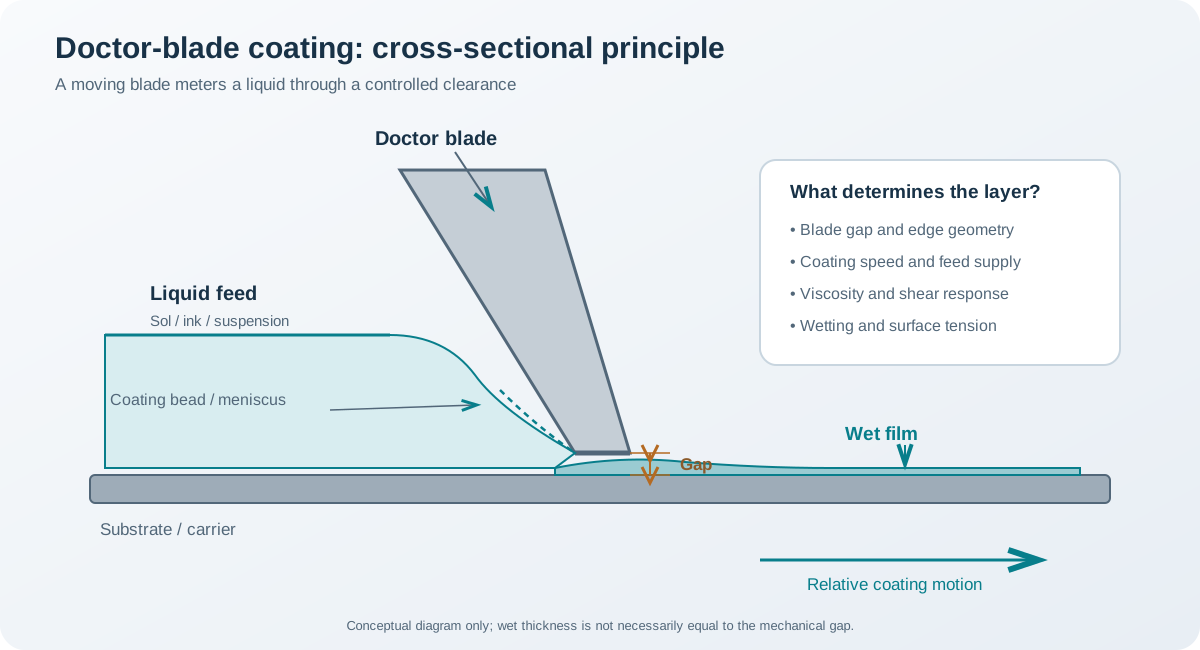
A controlled volume of liquid is placed in front of a blade. Either the blade moves over a stationary substrate or the substrate moves beneath a stationary blade. A wet layer forms downstream of the blade.
The process can be divided into: 1. Feed preparation: establish solution composition, homogeneity, viscosity and stability. 2. Dispensing: place a controlled amount of liquid ahead of the blade. 3. Blade passage: liquid flows through the blade–substrate gap and forms a coating bead or meniscus. 4. Film deposition: the moving substrate carries the wet layer away from the blade. 5. Drying and conversion: solvent evaporates and the deposited precursor forms a solid layer. 6. Characterization: measure thickness, uniformity, roughness, defects, adhesion and functional properties.
2. Blade configurations
2.1 Fixed-gap blade
The blade is held at a prescribed clearance above the substrate. The nominal gap is set mechanically, often using micrometre adjustment or calibrated spacers. The gap provides a geometric constraint, but it is not automatically equal to the wet-film thickness.
The deposited thickness also depends on: - coating speed; - liquid viscosity and its dependence on shear rate; - surface tension and contact-line behaviour; - blade angle and edge geometry; - liquid supply and reservoir shape; - substrate flatness and blade alignment.
This configuration is useful when a repeatable geometric setting is required, provided the gap is measured and the substrate is sufficiently flat.
2.2 Contact or near-contact blade
The blade edge may contact, or nearly contact, the substrate. The liquid is spread by a combination of hydrodynamic flow and mechanical metering. The blade load, edge condition and substrate roughness become important.
A contact configuration can produce thin films, but it also raises the risk of scratching, particle trapping, blade wear and local pressure variation. It is not appropriate for every fragile substrate or particle-containing feed.
2.3 Blade geometry and alignment
Blade thickness, edge sharpness, bevel angle, blade material and straightness can affect the coating bead and the resulting film. A blade that is not parallel to the substrate produces a transverse thickness gradient. Substrate waviness or particles beneath the carrier can create local variations even if the blade setting is nominally uniform.
For a wide coating, alignment should be checked across the full coating width rather than at one point only.
3. Blade gap is not the same as wet-film thickness
A common mistake is to assume that the final wet layer is always equal to the blade gap, or always a fixed fraction of it. Neither is generally correct.
The gap constrains the flow, but the deposited layer is formed by a dynamic meniscus. Depending on the apparatus and coating regime, part of the liquid can remain upstream, be displaced laterally, or form a bead whose shape changes with speed and rheology. A simple geometric estimate can be useful for initial setup, but it must be calibrated against measured wet or dry thickness.
For a fixed-gap arrangement, record at least: - nominal gap and how it was calibrated; - blade angle and edge configuration; - coating speed; - feed volume and dispense position; - solution temperature and rheological data; - substrate flatness and cleaning procedure.
The actual thickness should be mapped over the coated area. A single measurement near the centre cannot establish transverse or longitudinal uniformity.
4. Rheology of the coating liquid
The liquid must flow through the blade region without producing an unstable bead, streaks or edge defects. Its rheology is therefore a central process variable.
4.1 Newtonian and non-Newtonian behaviour
A Newtonian liquid has a viscosity that is approximately independent of shear rate under the conditions considered. Many polymer-containing sols, concentrated precursor solutions and particle suspensions are non-Newtonian.
For a shear-thinning liquid, apparent viscosity decreases as shear rate increases. This can facilitate flow through the blade gap, while the viscosity may recover after the liquid leaves the high-shear region. However, shear-thinning behaviour is not automatically beneficial: strong time dependence, thixotropy, yield stress or poor recovery can cause thickness variations and surface defects.
A simple power-law model is sometimes used over a limited shear-rate range:
[ =K^{n} ]
where () is shear stress, () is shear rate, (K) is the consistency index and (n) is the flow-behaviour index. For this model, (n<1) indicates shear-thinning, (n=1) Newtonian behaviour and (n>1) shear-thickening behaviour.
The corresponding apparent viscosity is:
[ _{app}==K^{n-1} ]
These equations describe a simplified constitutive model. Real coating liquids may require models that include yield stress, thixotropic recovery, viscoelasticity or shear-rate-dependent structure. Fit parameters should only be reported with the shear-rate range and measurement protocol.
4.2 What should be measured?
For a new feed, characterize: - viscosity versus shear rate at the relevant temperature; - up/down flow curves if thixotropy is suspected; - time-dependent viscosity or recovery after shear; - density and surface tension where relevant; - stability against sedimentation, aggregation or gelation; - pot life and sensitivity to temperature or solvent loss.
A viscosity value at one shear rate is not enough to describe a coating liquid that experiences a broad range of shear conditions.
5. Coating speed and flow regime
Increasing the relative speed between blade and substrate changes the flow field and the time available for liquid redistribution. The resulting wet thickness may increase or decrease depending on the geometry and operating regime; there is no universal monotonic rule that applies to all blade coaters.
At low speed, capillary forces, contact-line pinning and liquid supply can dominate. At higher speed, viscous entrainment and dynamic wetting become increasingly important. If the feed cannot replenish the coating bead at the required rate, the meniscus may become unstable and produce ribbing, streaks or coating failure.
A useful experimental approach is to construct a speed–gap map: 1. Select a small set of calibrated gaps. 2. For each gap, vary coating speed over a controlled range. 3. Keep solution age, temperature, dispense volume and substrate condition fixed. 4. Measure wet or dry thickness at multiple positions. 5. Record the onset of streaking, ribbing, edge instability or dewetting. 6. Repeat selected conditions to assess reproducibility.
Do not optimize speed from thickness alone. A nominally correct average thickness may conceal unacceptable edge build-up or local defects.
6. Estimating dry-film thickness
The dry thickness depends on the non-volatile material delivered per unit area, the density and porosity of the final layer, and any material lost during drying or thermal conversion.
A useful mass-balance expression is:
[ h_{dry}= ]
where: - (h_{dry}) is the dry-film thickness; - (m_{NV}) is the retained non-volatile mass; - (A) is the coated area; - (_{film}) is the effective density of the dried film.
This estimate assumes a reasonably uniform layer and a known retained mass and density. If the layer is porous, compositionally graded or incompletely converted, the effective density must reflect that state. If the film loses material during decomposition, the retained non-volatile mass must be measured or estimated from a justified mass balance.
The expression is more physically meaningful than converting blade gap directly into dry thickness. For process development, compare calculated thickness with profilometry, ellipsometry or cross-sectional microscopy as appropriate.
7. Drying and sol-gel conversion
After deposition, the liquid layer loses solvent and develops mechanical integrity. The drying path can be as important as the blade settings.
7.1 Evaporation and stress
Solvent evaporation produces concentration gradients and shrinkage. If the upper surface dries faster than the interior, a skin may form and hinder further solvent transport. The resulting stress can cause cracks, wrinkles, blisters or delamination.
The risk is affected by: - wet-film thickness; - solvent volatility and mixture composition; - substrate temperature; - airflow and ambient humidity; - sol-gel reaction and gelation rate; - substrate wetting and adhesion; - the mechanical properties of the developing network.
A staged drying programme may reduce abrupt gradients, but its suitability must be tested against the chemistry and substrate. There is no universal drying temperature or time.
7.2 Thermal treatment
For an inorganic sol-gel film, subsequent heating may remove organic residues, complete condensation, densify the layer or promote crystallization. Select the thermal schedule using the precursor chemistry, thermal analysis and substrate limits.
Separate the objectives of solvent removal, organic decomposition, network conversion and crystallization. A single high-temperature step may cause rapid gas evolution or excessive shrinkage. Thermal-expansion mismatch can also generate stress during heating and cooling.
8. Defects and troubleshooting
| Observation | Possible causes | Diagnostic checks |
|---|---|---|
| Longitudinal streaks | Blade contamination, edge damage, particles or unstable bead | Inspect and clean blade; check feed dispersion and filtration compatibility |
| Transverse thickness gradient | Blade not parallel, substrate tilt or non-uniform gap | Map gap across width; verify substrate flatness and alignment |
| Ribbing or periodic bands | Hydrodynamic instability, speed/gap combination or rheology | Examine speed dependence and rheological flow curve |
| Bare regions or dewetting | Poor substrate wetting, contamination or incompatible surface chemistry | Check cleaning, contact angle and solution compatibility |
| Edge beads | Lateral flow and surface-tension-driven accumulation | Inspect edge geometry and coating width; adjust feed and boundary conditions |
| Pinholes | Entrained air, bubbles, contamination or local dewetting | Degas where appropriate; inspect solution and substrate |
| Mud cracks after drying | Excessive wet loading, shrinkage stress or rapid drying | Reduce per-pass thickness and control drying rate |
| Blisters | Trapped solvent or rapid gas evolution | Review drying and thermal mass-loss behaviour |
| Poor adhesion | Inadequate wetting, contamination or thermal mismatch | Reassess surface preparation and full thermal cycle |
| Thickness drifts during a run | Solvent loss, feed ageing, temperature drift or changing blade condition | Monitor feed properties and environmental conditions |
A defect’s direction and spatial distribution provide clues. Continuous streaks in the coating direction often point to blade or feed problems, whereas a systematic transverse gradient suggests alignment or gap variation.
9. Process-development workflow
- Define the target: substrate, coating width, final thickness, roughness, coverage and functional requirement.
- Prepare the substrate: establish a repeatable cleaning and drying procedure.
- Qualify the feed: composition, solids content, viscosity curve, surface tension where relevant, stability and ageing.
- Calibrate the coater: verify gap, blade straightness, alignment and substrate flatness.
- Establish a baseline: fix the feed volume, coating speed, temperature and blade geometry.
- Screen gap and speed: vary controlled parameters and measure thickness and defect density.
- Optimize drying: evaluate solvent removal and shrinkage without changing the coating variables simultaneously.
- Apply thermal conversion: use thermal evidence and substrate constraints.
- Map the final film: measure thickness at multiple positions and characterize morphology, phase, composition and adhesion.
- Verify reproducibility: repeat independent runs and report the variation.
For experimental design, separate deposition variables from drying and conversion variables. Otherwise, a change in final thickness may be incorrectly attributed to the blade when it actually results from a different drying history.
10. Characterization
| Property | Methods | Notes |
|---|---|---|
| Wet-film thickness | Wet-film gauge or optical methods where suitable | Measurement can disturb soft or reactive films |
| Dry-film thickness | Profilometry, ellipsometry, reflectometry, cross-sectional SEM | State the measurement model and sampling positions |
| Thickness uniformity | Multi-point mapping or line scans | Include centre, edges and coating direction |
| Surface morphology | Optical microscopy, SEM, AFM | Report field of view and resolution |
| Roughness | AFM or profilometry | State Ra/Rq and scan dimensions |
| Phase | XRD or grazing-incidence XRD | Thin-film geometry and substrate background matter |
| Chemical conversion | FTIR, Raman, XPS or thermal analysis | Select method based on the chemistry and sampling depth |
| Adhesion | Scratch, tape or pull-off methods | Report protocol and failure mode |
| Functional response | Application-specific electrical, optical, catalytic or barrier test | Link the test to the intended use |
11. Blade coating compared with neighbouring methods
| Method | How the liquid is delivered | Main thickness controls | Typical distinction |
|---|---|---|---|
| Doctor-blade coating | Liquid placed ahead of a blade and spread through a gap | Gap, speed, rheology, bead stability | Simple adjustable laboratory coating |
| Slot-die coating | Metered liquid supplied through a precision die slot | Flow rate per width and substrate speed, plus coating window | Pre-metered delivery and low material waste |
| Spin coating | Liquid spread by rotation | Spin-speed programme, dispense and evaporation | Suited to flat, rotatable substrates |
| Dip coating | Substrate withdrawn from a liquid bath | Withdrawal speed, viscosity and surface tension | Meniscus-controlled coating |
| Spray coating | Atomized droplets transported to a surface | Droplet distribution, spray flux, distance and substrate conditions | Suitable for complex geometries and selected large-area routes |
Blade coating is not a substitute for slot-die coating in every application. Slot-die systems meter the incoming liquid through a die, while conventional blade coating relies more directly on the moving blade and coating bead. The process windows and scale-up considerations therefore differ.
12. Minimum reporting checklist
A reproducible report should state: - substrate material, dimensions, flatness and surface preparation; - feed composition, concentration basis, solvent and preparation sequence; - solution age, temperature and rheological characterization; - blade type, material, edge geometry and angle; - nominal gap and calibration method; - coating speed and direction; - feed volume, dispense position and coating width; - ambient temperature, humidity and airflow; - drying and thermal-conversion conditions; - thickness measurement technique, positions and uncertainty; - surface morphology, roughness, adhesion and functional properties; - replicate count and run-to-run variation.
References
- J. H. Yoo, M. H. Lee, S. H. Lee and J. H. Park, “Scalable Deposition Methods for Large-area Production of Perovskite Thin Films,” Energy & Environmental Materials (2019). https://doi.org/10.1002/eem2.12043. The review discusses blade coating as a directional coating method and compares it with other scalable deposition routes.
- X. Ding, J. Liu and T. A. L. Harris, “A review of the operating limits in slot die coating processes,” AIChE Journal 62 (2016), 2508–2524. https://doi.org/10.1002/aic.15268. This is a neighbouring pre-metered coating method; its operating-window concepts are useful for understanding coating-bead stability, but its equations should not be transferred directly to blade coating.
- M. Guillon et al., “Tuning the Microstructure and Thickness of Ceramic Layers with Advanced Coating Technologies Using Zirconia as an Example,” Advanced Engineering Materials (2020). https://doi.org/10.1002/adem.202000529. A comparative review of coating technologies for ceramic layers.
- M. Jabbari, R. Bulatova, A. I. Y. Tok, C. R. H. Bahl, E. Mitsoulis and J. H. Hattel, “Ceramic tape casting: A review of current methods and trends with emphasis on rheological behaviour and flow analysis,” Materials Science and Engineering: B 212 (2016), 39–61. https://doi.org/10.1016/j.mseb.2016.07.011. Included for the related blade-based ceramic process; tape casting is not identical to solution-film doctor-blade coating.
- J. Hotza et al., “Tape casting of preceramic polymers toward advanced ceramics: A review,” International Journal of Ceramic Engineering & Science (2019). https://doi.org/10.1002/ces2.10009. Discusses slurry preparation, degassing, casting, drying and subsequent processing in tape casting.
Scope note: The blade gap is a machine setting, not a universal direct measurement of wet-film thickness. Establish a calibration curve for the actual blade, feed, speed and substrate combination, and measure the final film after drying and thermal conversion.