Wastewater System Inspection
Wastewater System Inspection
A field-oriented method for tracing wastewater streams, examining treatment units, checking operating records and evaluating sampling evidence. The actual permit, process design and applicable jurisdiction determine the required controls and discharge criteria.
## 1. Map all wastewater streams
Start by identifying where water is used and where it leaves each process. Separate streams where the facility design and permit require it.
| Stream | Possible origin | Inspection focus |
|---|---|---|
| Process wastewater | Washing, rinsing, reaction, product finishing | Chemicals used, batch variability and pretreatment |
| Cooling water | Cooling towers and heat exchangers | Recirculation, blowdown and contamination risk |
| Boiler blowdown | Boiler operation | Discharge route, temperature and treatment |
| Domestic sewage | Toilets, kitchens and welfare facilities | Separate collection and treatment route |
| Stormwater | Roofs, yards and exposed storage | Contact with materials, spills and drainage |
| Cleaning wastewater | Equipment and floor washing | Detergents, oils, solids and intermittent loads |
Prepare a simple stream inventory with the source, approximate flow, collection point, treatment route and final destination. If flow data are unavailable, record that limitation instead of estimating a value without a basis.
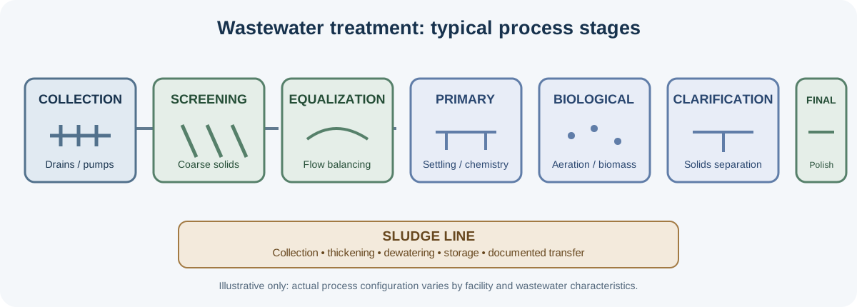
## 2. Follow the treatment train
Treatment systems differ by industry and design. A plant may not contain every stage below.
| Stage | Purpose | Practical inspection points |
|---|---|---|
| Collection and screening | Convey wastewater and remove coarse solids | Screens, bypasses, pumps, blockages and housekeeping |
| Grit removal | Remove dense inorganic particles | Grit accumulation and removal arrangements |
| Equalization | Smooth flow and concentration variation | Mixing, level control, odor and overflow protection |
| pH adjustment / chemical treatment | Condition wastewater and remove selected contaminants | Chemical identity, dosing, storage, mixing and pH records |
| Primary clarification | Settle suspended solids | Sludge withdrawal, scum removal and short-circuiting |
| Biological treatment | Reduce biodegradable organic matter | Aeration or mixing, biomass condition and operating logs |
| Secondary clarification | Separate biological solids | Sludge blanket, return sludge and solids carryover |
| Tertiary treatment / disinfection | Provide additional polishing where required | Filter condition, disinfectant control and residual monitoring |
| Sludge treatment | Reduce water content and manage residual solids | Thickening, dewatering, storage and transfer records |
## 3. Inspect operation, not just equipment presence
For each unit, record its equipment ID, operating state, observed condition and any available process reading. Compare field conditions with the process-flow diagram and operating logs.
Mechanical and electrical equipment - Pumps: operating status, leakage, abnormal noise, vibration and standby availability. - Blowers: operating status, air delivery indicators, unusual noise and maintenance history. - Mixers: operation, visible dead zones and mechanical condition. - Dosing pumps: chemical feed, calibration or verification records, tubing condition and secondary containment. - Sensors: identification, calibration status, alarms and consistency with logged readings.
Process observations - Unexpected odor, color, foam, floating material or solids carryover. - Overflow, bypass, leakage, stagnant zones or evidence of untreated discharge. - Unusual sludge accumulation or poor sludge dewatering. - Chemical storage problems, incompatible storage or missing spill controls. - Differences between the actual pipework and the documented flow diagram.
An observation may indicate a need for further investigation; it is not automatically proof of a permit violation.
## 4. Sampling locations and monitoring design
Choose sampling points to answer a defined question. Typical locations include:
- Influent: characterizes incoming load and variability.
- Intermediate stages: helps diagnose treatment performance when troubleshooting.
- Final effluent: assesses the quality at the relevant compliance or discharge point.
- Receiving environment: used only where the monitoring plan or applicable requirement calls for it.
The sampling point must represent the stream being assessed. Record whether the sample is grab or composite, the sampling time or compositing period, operating conditions, weather where relevant, and any unusual process event.
### Common wastewater parameters
| Parameter | What it indicates | Important note |
|---|---|---|
| pH | Acidity / alkalinity | May change rapidly; measurement and preservation requirements are method-specific |
| Temperature | Thermal condition | Record at the point and time of collection |
| Electrical conductivity (EC) | Ionic content indicator | Not a direct measurement of a specific contaminant |
| Total suspended solids (TSS) | Particulate matter | Sampling and mixing affect representativeness |
| BOD₅ | Biodegradable oxygen demand | Requires controlled laboratory incubation |
| COD | Chemically oxidizable matter | Method, interferences and digestion conditions matter |
| Dissolved oxygen (DO) | Oxygen available in water | Particularly useful at selected biological-treatment and receiving-water points |
| Oil and grease | Extractable oily material | Requires appropriate containers and method-specific handling |
| Nutrients | Nitrogen and phosphorus species | Select species according to process and permit |
| Metals | Selected dissolved or total metals | Container, filtration and preservation depend on the analytical method |
Parameter selection must follow the permit, industrial activity, receiving environment and monitoring objective. Do not treat this table as a universal regulatory list.
## 5. Sampling quality and chain of custody
A result is only useful when the sample is representative and its identity and handling are controlled.
- Prepare a sampling plan that defines points, parameters, methods, containers, preservation and holding times.
- Use clean, method-appropriate containers and avoid cross-contamination between samples.
- Label each sample with a unique ID, location, date and time, sampler and requested analysis.
- Record field measurements separately from laboratory results.
- Preserve, cool and transport samples as required by the selected analytical method.
- Include field blanks, duplicates or other quality-control samples when specified by the plan.
- Maintain chain-of-custody documentation from collection to laboratory receipt.
- Use competent personnel and a laboratory operating under the relevant quality requirements.
Never select a preservative, holding time or container from memory alone. Follow the validated method and laboratory instructions. Do not collect samples from unsafe or inaccessible locations without the required authorization, risk assessment and equipment.
## 6. Review operating and laboratory records
Compare records with the physical plant and the facility’s operating pattern.
- Flow records and meter status.
- pH, DO, temperature and other online monitoring logs where installed.
- Chemical consumption and dosing records.
- Pump, blower, mixer and sensor maintenance.
- Laboratory reports, analytical methods and quality-control information.
- Sludge production, storage, transfer and destination records.
- Bypass, overflow, shutdown, upset and corrective-action records.
- Discharge authorization and applicable monitoring schedule.
Look for gaps, unusual repeated values, missing units, inconsistent sampling points, results outside expected operating ranges and records that do not match the plant’s actual configuration.
## 7. Troubleshooting observations
These are prompts for further investigation, not diagnoses on their own.
| Observation | Possible areas to investigate |
|---|---|
| Low or unstable DO in an aeration basin | Blower operation, air distribution, loading, sensor condition and process control |
| High TSS in final effluent | Clarifier operation, sludge settling, hydraulic loading and solids carryover |
| Sudden pH variation | Influent batch changes, chemical dosing, probe calibration and equalization |
| Persistent foam | Process characteristics, surfactants, biological conditions and operating changes |
| Strong or unusual odor | Anaerobic zones, stagnant wastewater, chemical handling and ventilation |
| High COD or BOD result | Influent variability, treatment performance, sampling representativeness and laboratory QA/QC |
| Sludge dewatering difficulty | Sludge characteristics, conditioning, equipment operation and polymer dosing |
Confirm the cause with appropriate process data, repeat observations or valid analytical work before drawing a conclusion.
## 8. Practical wastewater inspection checklist
### Collection and flow - [ ] Wastewater streams and generation points identified. - [ ] Process wastewater, domestic sewage and stormwater routes distinguished. - [ ] Flow diagram compared with actual pipework and drains. - [ ] Bypasses, overflows, leaks and undocumented connections checked.
### Treatment operation - [ ] Installed treatment stages and equipment IDs recorded. - [ ] Pumps, blowers, mixers and dosing systems checked. - [ ] Operating readings and logs reviewed. - [ ] Chemical storage and spill controls examined. - [ ] Sludge handling and storage inspected.
### Sampling and records - [ ] Sampling points and monitoring purpose identified. - [ ] Sample type, time and operating conditions documented. - [ ] Containers, preservation and holding times confirmed with the method/lab. - [ ] Sample IDs and chain-of-custody records checked. - [ ] Laboratory methods, units and quality-control information reviewed.
### Discharge and close-out - [ ] Final discharge or reuse point identified. - [ ] Results compared with the correct current permit requirement. - [ ] Operational observations distinguished from confirmed analytical exceedances. - [ ] Missing information and follow-up actions listed.
## 9. Example of an evidence-based observation
Illustrative example — not a real facility finding
During a site walkthrough, the wastewater equalization tank was observed with its mixer stopped. The equipment tag and time were recorded, and the operator stated that the mixer had been unavailable since the previous shift.
Appropriate follow-up would include checking the maintenance log, confirming the duration and process impact, reviewing any operating response and determining whether additional measurements are needed. The observation alone does not establish an effluent-limit exceedance.
## 10. Reporting structure
A wastewater inspection report can include:
- Facility and treatment-system description.
- Wastewater stream inventory and flow diagram.
- Treatment units inspected and operating conditions.
- Sampling locations, methods, IDs and chain-of-custody details.
- Laboratory results with units, methods and QA/QC notes.
- Comparison with the applicable permit requirements.
- Evidence-based observations and unresolved information.
- Corrective actions and follow-up verification.
## Safety and regulatory note
Follow site access controls, chemical-handling procedures, electrical safety requirements and confined-space rules. Do not enter tanks, pits or manholes without a formal confined-space entry program. Regulatory limits and sampling frequencies must be verified against the current permit and the relevant jurisdiction.